Magnetic lens apparatus for use in high-resolution scanning electron microscopes and lithographic processes

a scanning electron microscope and high-resolution technology, applied in the field of magnetic lens apparatus, can solve the problems of somewhat compromised design of dipole lens for transmission microscope, and achieve the effect of facilitating the construction of sem, high resolution, and large angle tilting of specimen stages

Inactive Publication Date: 2002-06-25
ARCH DEVMENT
View PDF12 Cites 32 Cited by
  • Summary
  • Abstract
  • Description
  • Claims
  • Application Information

AI Technical Summary

Benefits of technology

An important practical advantage of the invention is that the lens apparatus disclosed herein may be conveniently fitted into an electron beam apparatus so as to leave the whole space between the source of charged particles and the target position around the beam of charged particles available for placing large specimens, and / or a secondary electron detector or "light pipe."
is that the lens apparatus disclosed herein may be conveniently fitted into an electron beam apparatus so as to leave the whole space between the source of charged particles and the target position around the beam of charged particles available for placing large specimens, and / or a secondary electron detector or "light pipe."
If the specimen is very thin or if it has holes in it then it may be possible for some of the incident electrons to strike the pole piece and generate electrons. This may produce some background noise. However, because the incident electrons have such low energies penetration should be a rare occurrence but a thin coating of carbon or other suitable material on the iron pole piece will reduce the background by a large factor. Methods for coating carbon onto the pole piece are well known to those of skill in the art (e.g., by using a vacuum evaporator). It should be noted that the bare pole piece itself may serve as a specimen in its own right, which will be very useful for the purposes of column alignment and the like.
Regarding the field of view, particularly at low magnifications, concern arises because of the sharp radius of curvature of the pole piece. Electron optics suggest that other third order aberrations may become important, such as coma, astigmatism, distortion and curvature of field. Mechanisms for controlling such aberrations have been previously published (Crewe and Parker, 1976). At most this would involve some additional electronics. Dynamic stigmation presents no problem and distortion may be controlled in exactly the same way as it is done in TV sets, by adding nonlinear terms to the scan voltage. Curvature of field can be controlled by dynamically changing the virtual focus of the incident electron beam. For a fast scan this may be best accomplished by adjusting the middle electrode of a three-element electron gun. For slow scans it is also convenient to adjust the current in a condenser lens.
The size of the magnetic lens may be significantly reduced by comparison with conventional lenses by providing the coil with cooling means located, for example, within the layer of magnetic material or within the structure of the coil, thereby allowing a required magnetic field to be generated by a larger electric current flowing in a smaller number of turns of wire.
When desirable, the specimen stage and / or specimen holder may be cooled by ambient dissipation of heat energy, or alternatively by flowing a cooling solution around the specimen housing in a manner analogous to that of cooling the lens apparatus itself. Such a cooling fluid may be water, glycol, polyethylene glycol, liquid nitrogen, or other such suitable fluid. The use of a cooled specimen stage may be particularly desirable in the case of biological specimens.

Problems solved by technology

It was postulated that such lenses would have smaller aberration coefficients than conventional lenses, however the design of dipole lenses for transmission microscopes is somewhat compromised by the need to provide a hole in the pole piece for the passage of the electron beam.

Method used


Image

  • Magnetic lens apparatus for use in high-resolution scanning electron microscopes and lithographic processes
  • Magnetic lens apparatus for use in high-resolution scanning electron microscopes and lithographic processes
  • Magnetic lens apparatus for use in high-resolution scanning electron microscopes and lithographic processes

Examples


example 1

5.1 Example 1

Lens Apparatus Comprising a Solid Pole Piece

The present example concerns the general description of a low-voltage SEM particularly useful in the analysis of biological and other fragile specimens which comprises a magnetic lens apparatus having a solid pole piece.

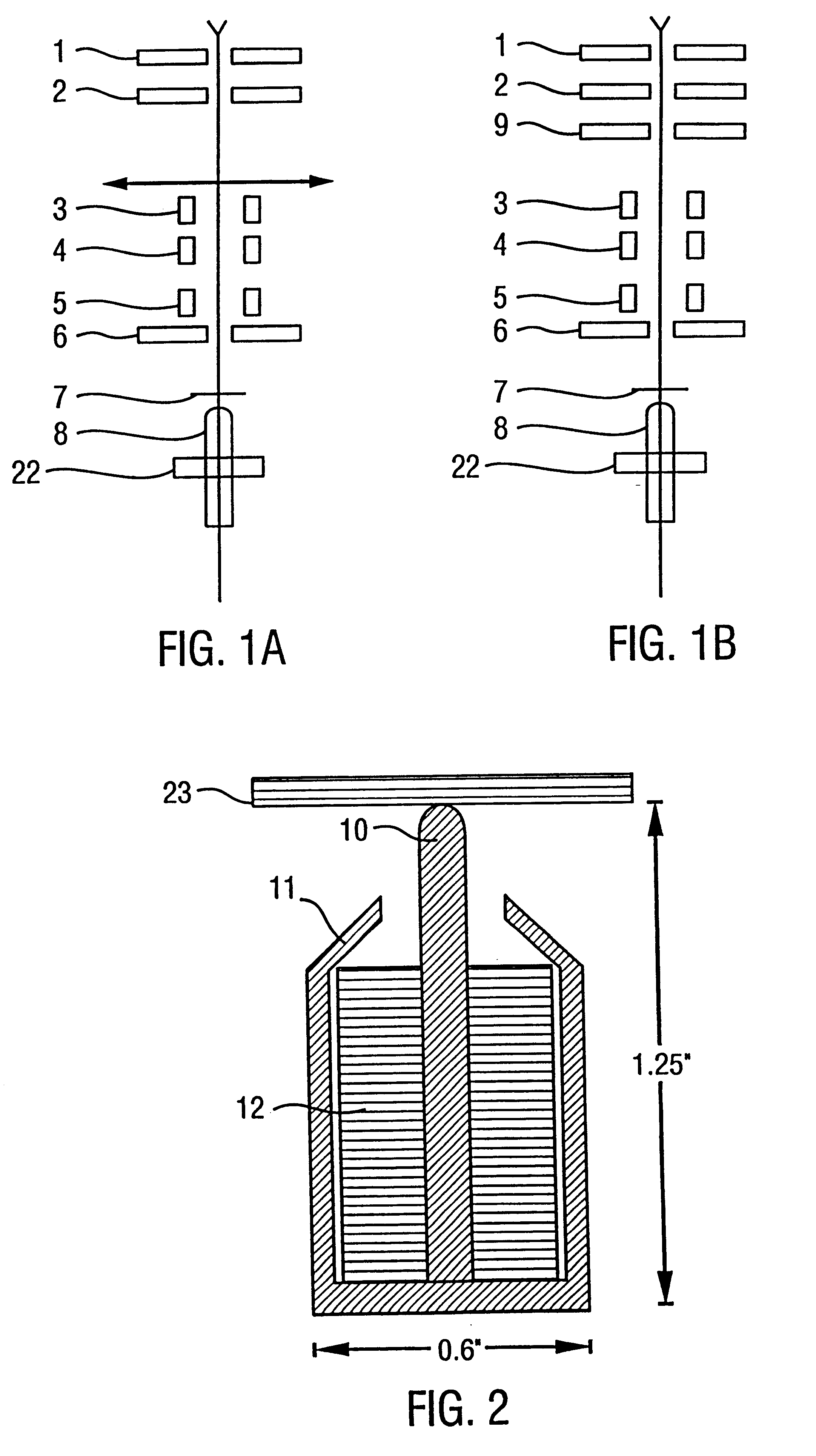
5.1.1 Schematic View of Solid-Pole Piece Lens Apparatus

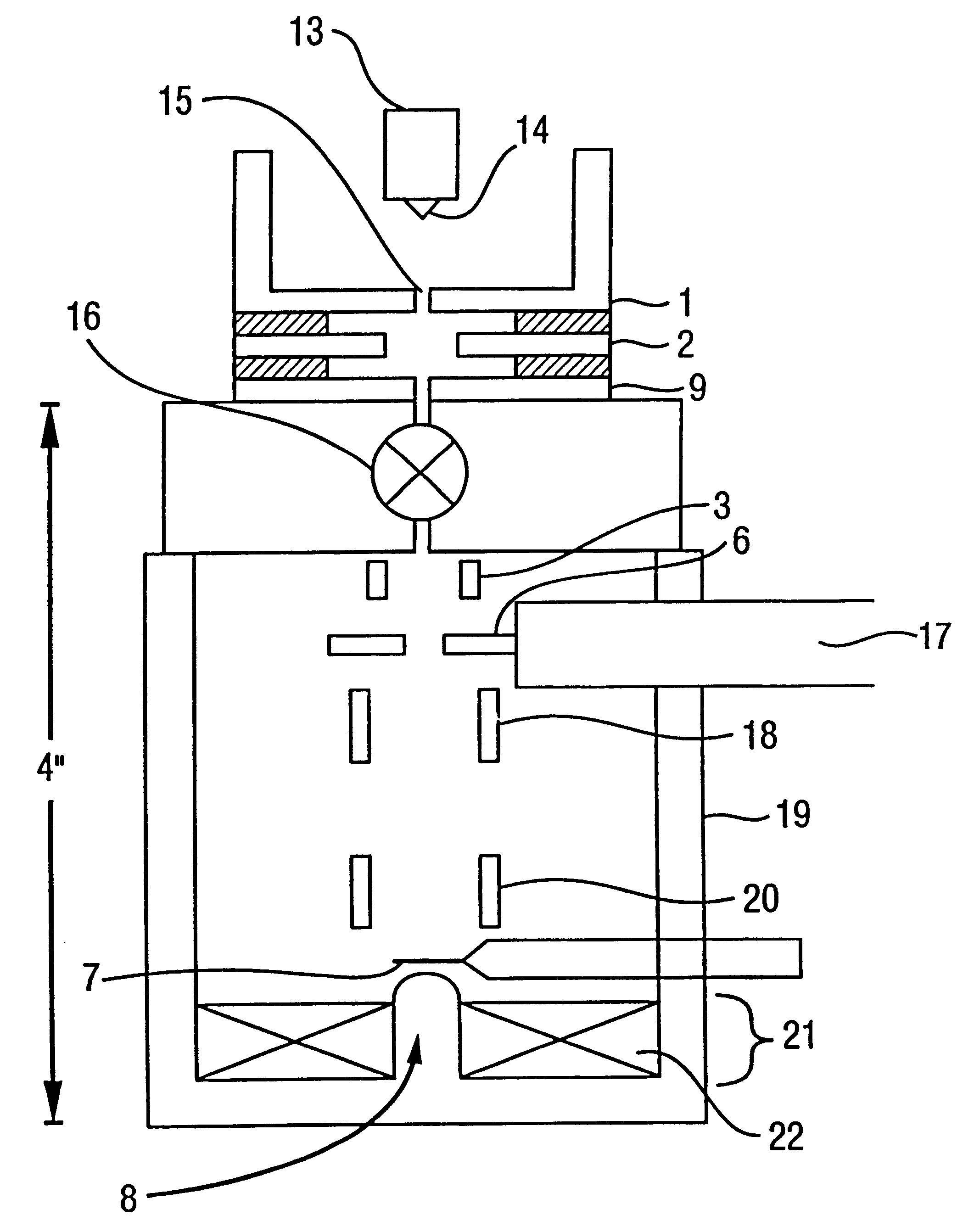
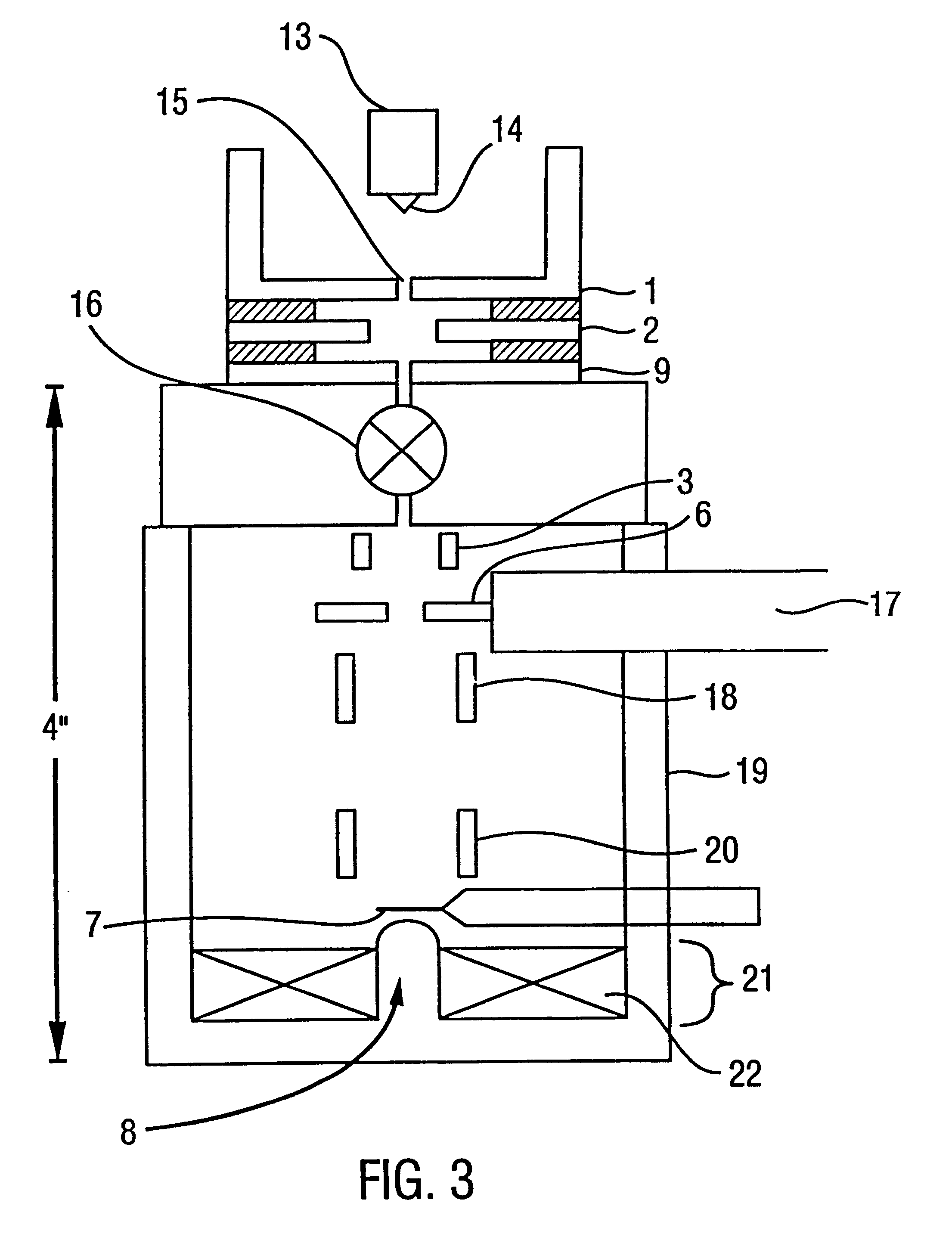
Schematic cross-sectional diagrammatic views of the components of either a two anode (FIG. 1A) or three anode (FIG. 1B) illustrate the preferred elements of a SEM employing one of the disclosed lens apparatus. A full-scale view of an SEM employing the lens apparatus of the present invention is shown in FIG. 3.

Referring to FIG. 3, a beam of electrons are produced from the tip 14 of a field emission source 13. Said beam passes through an aperture 15 and is accelerated by a first anode 1, a second anode 2, and optionally a third anode 9. A valve 16 isolates the vacuum of the gun from that of the rest of the column. Concentric with the axis of the beam produced...

example 2

5.2 Example 2

Electron Focusing Using Dipole Lenses

In addition to the lens apparatus of Example 1, having noted that a magnetic dipole made an excellent focusing lens for a low energy electrobeam when placed below the specimen rather than above it, the inventor began to consider additional ways in which such a dipole lens could be fabricated.

This example describes the inventor's demonstration of the electron optics related to the construction of the lens apparatus herein which employ magnetic dipoles, and virtual magnetic monopoles.

5.2.1 Magnetic Field Strength

When one considers a magnetic dipole which produces a magnetic field distribution which is symmetrical about the axis (which the inventor calls the z-axis) the magnitude of the magnetic field strength is given by ##EQU10##

where .mu. is the dipole moment, with dimension Tesla m.sup.3.

If one considers a beam of electrons which is parallel to the axis at infinity and which is incident on the dipole, the focal properties of a dipol...

example 3

5.3 Example 3

Lens Apparatus Comprising a Magnetized Sphere

This example relates to the use of permanent magnets in fabrication of dipole magnetic lens apparatus.

It is quite possible and indeed it is very simple to manufacture a sphere of magnetic material which is permanently magnetized along one diameter. This can be done using material such as AlNiCo.TM. or any of the more modern materials which are commercially available such as the rare-earth magnets of which samarium-cobalt is typical. The fabrication of such materials are well-known to those of skill in the art. They can be made in a variety of forms and it is presumed the manufacturing of them in the form of small spheres is a straightforward matter. With regard to the magnetic field strength which could be obtained in this way, it should be pointed out that a magnetized sphere has a large demagnetization field and therefore the full saturation value of the material cannot be reached. However, calculations indicated that it wa...


PUM


Abstract

Disclosed are lens apparatus in which a beam of charged particles is brought to a focus by means of a magnetic field, the lens being situated behind the target position. In illustrative embodiments, a lens apparatus is employed in a scanning electron microscope as the sole lens for high-resolution focusing of an electron beam, and in particular, an electron beam having an accelerating voltage of from about 10 to about 30,000 V. In one embodiment, the lens apparatus comprises an electrically-conducting coil arranged around the axis of the beam and a magnetic pole piece extending along the axis of the beam at least within the space surrounded by the coil. In other embodiments, the lens apparatus comprises a magnetic dipole or virtual magnetic monopole fabricated from a variety of materials, including permanent magnets, superconducting coils, and magnetizable spheres and needles contained within an energy-conducting coil. Multiple-array lens apparatus are also disclosed for simultaneous and / or consecutive imaging of multiple images on single or multiple specimens. The invention further provides apparatus, methods, and devices useful in focusing charged particle beams for lithographic processes.

Description

1. BACKGROUND OF THE INVENTION1.1 Field of the InventionThe present invention relates to magnetic lens apparatus comprising magnetic monopoles or magnetic dipoles useful for focusing a beam of charged particles, such as electrons, onto a target in front of the lens. More particularly, the invention concerns magnetic lenses which may be positioned below the specimen in a scanning electron microscope, which have magnetic field strengths on the order of between about 0.5 and 10 Tesla. Disclosed are lenses optimized for high-resolution focusing of an electron beam having an accelerating voltage of between about 10 and about 50,000 V. In a preferred embodiment, the lens apparatus disclosed herein provide the sole focusing lens for a low-voltage (10 to 10,000 V) high-resolution scanning electron microscope. Alternative embodiments employing superconducting coil technologies for producing a magnetic field in such lens apparatus are also disclosed as are methods for their use in variable-pr...

Claims


Application Information

Patent Timeline
Patent Type & Authority Patents(United States)
IPC IPC(8): H01J37/10H01J37/141G01Q10/00G01Q30/02
CPCH01J37/1416H01J2237/28H01J2237/1035
Inventor CREWE, ALBERT V.
Owner ARCH DEVMENT
Why Eureka
Try Eureka