Wellbore circulation system

a circulation system and wellbore technology, applied in the direction of drilling pipes, wellbore/well accessories, sealing/packing, etc., can solve the problems of formation damage, mud circulation stops and has to be re-started, and achieve the effect of fast connection tim

Inactive Publication Date: 2002-07-02
WEATHERFORD TECH HLDG LLC
View PDF43 Cites 191 Cited by
  • Summary
  • Abstract
  • Description
  • Claims
  • Application Information

AI Technical Summary

Benefits of technology

In certain embodiments of systems and methods according to the present invention, faster connection time is achieved. In certain particular aspects in underbalanced drilling with single-phase or two-phase fluids in the wellbore, the need for check valves (or "string floats") in a drill string is reduced or eliminated; gas pockets do not need to be rented; and continuous fluid circulation can be maintained. There is no need to wait while circulation is shut off to let gas pressure in the wellbore balance with the atmosphere before a conne...

Problems solved by technology

Interruption of drilling may mean that the circulation of the mud stops and has to be re-started when drilling resumes.
This can be time consuming, can cause deleterious effects on the walls of the well being drilled, and can lead to formation damage and problems in maintaining an open wellbore.
The weighting...

Method used


Image

  • Wellbore circulation system
  • Wellbore circulation system
  • Wellbore circulation system

Examples


Embodiment Construction

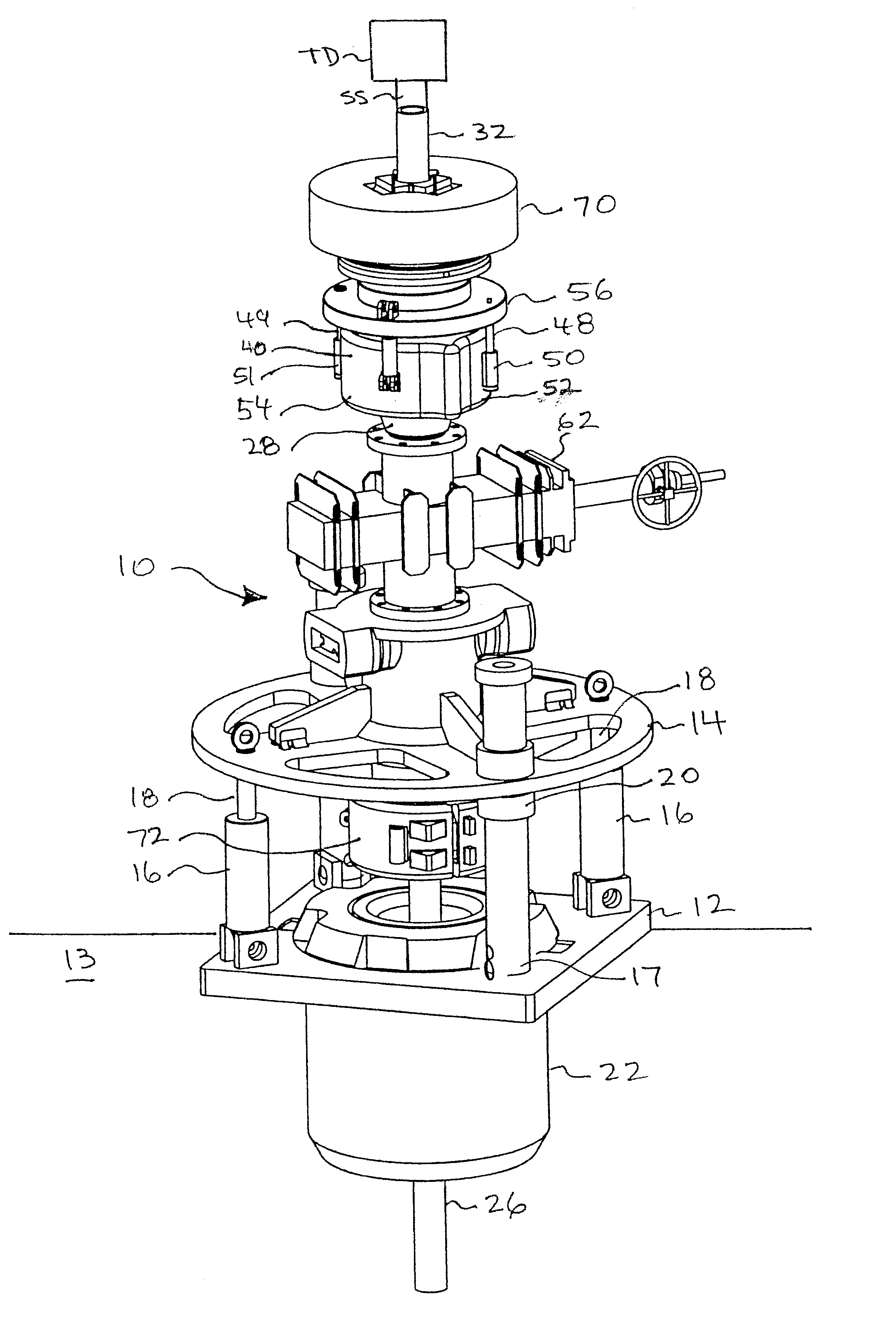
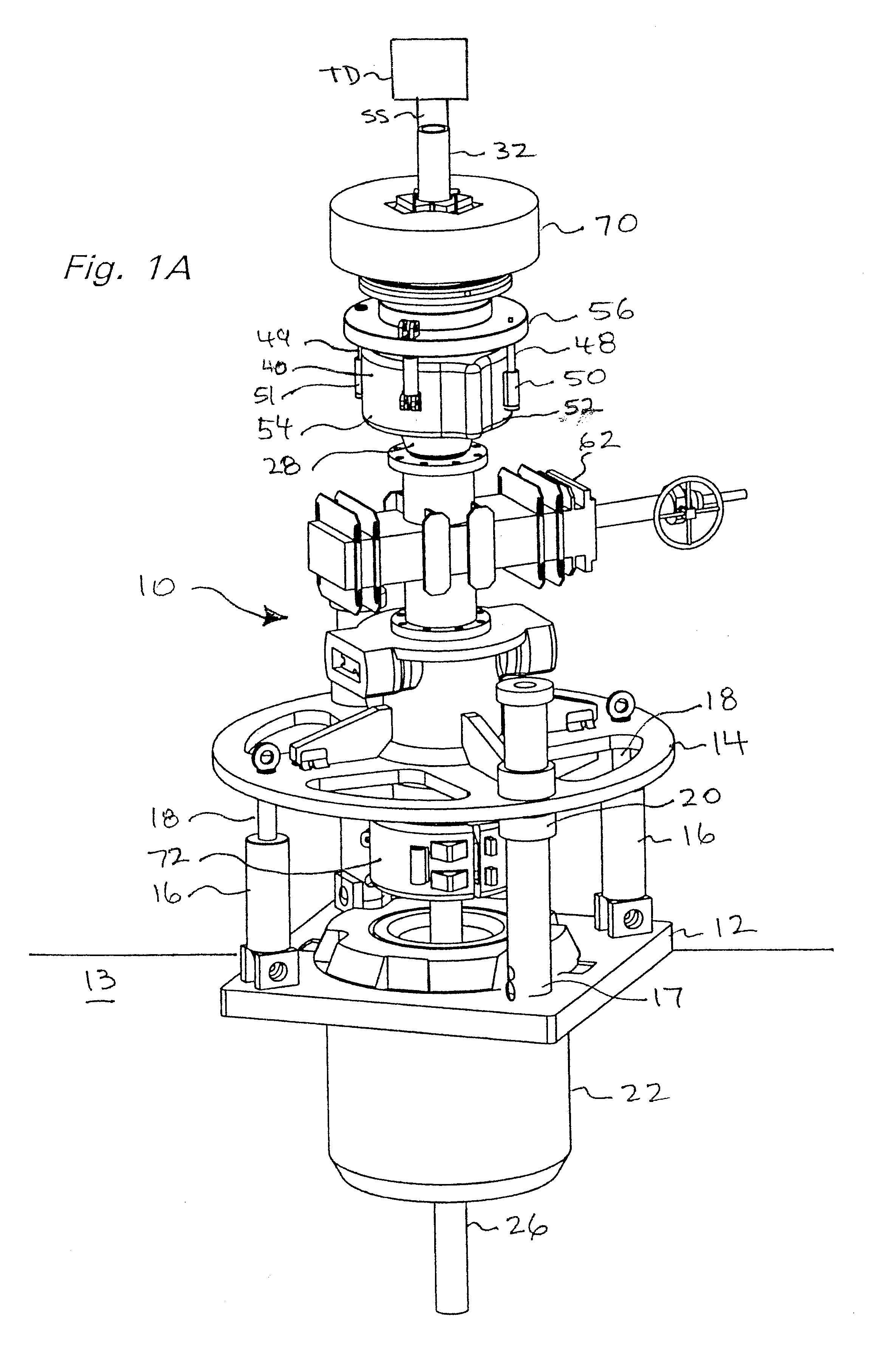
FIGS. 1A-2 show a system 10 according to the present invention with a platform 12 mounted above a rotary table 13 and a platform 14 movably mounted to and above the platform 12. Two cylinders 16 each has a movable piston 18 movable to raise and lower the platform 14 to which other components of the system 10 are connected. Any suitable piston / cylinder may be used for each of the cylinders 16 / pistons 18 with suitable known control apparatuses, flow lines, consoles, switches, etc. so that the platform 14 is movable by an operator or automatically. Guide posts 17 (one shown in FIG. 1A) secured to the platform 12 move through tubulars 20 of the platform 14 to guide and control movement of the platform 14. Optionally, a top drive TD is used to rotate the drill string. An optional saver sub SS is interconnected between the top drive and the drill string.

A spider 22 including, but not limited to, known flush-mounted spiders, or other apparatus with selectively emplaceable slips extends ben...


PUM


Abstract

A system for continuously circulating fluid to and through a tubular string either of coiled tubing or made up of a plurality of tubulars connected end-to-end while an upper tubular is added to or removed from a top tubular of the plurality of tubulars, all tubulars having a top-to-bottom fluid flow channel therethrough, the system having an upper chamber with a bottom opening, a top opening, and an upper sealing apparatus for sealingly encompassing a portion of the upper tubular, a lower chamber with a bottom opening, a top opening and a lower sealing apparatus for sealingly encompassing a portion of the top tubular, one of the upper chamber and the lower chamber sized for accommodating connection and disconnection therein of the upper tubular and the top tubular, and gate apparatus between and in fluid communication with the upper chamber and the lower chamber. Such a system may have apparatus for isolating a tubular therein from an axial load imposed by fluid pressure in a chamber; at least one of the lower chamber and the upper chamber with inner bushing apparatus with a portion thereof movably disposable within the chamber's sealing apparatus for facilitating movement of a tubular with respect to the chamber's sealing apparatus, and the system connectible to and rotatable by a rotating system for rotating the tubular string; and/or heave compensation interconnections for interconnecting the system to an offshore rig's heave compensation system. The system in certain aspects including fluid flow lines to each of the top and bottom chambers, a supply of fluid for circulating through the tubular string and through the upper and lower chambers, apparatus for continuously moving circulating fluid from the supply through the system into the tubular string.

Description

1. Field of the InventionThis invention is related to systems and methods for continuously circulating fluid through two tubulars as they are being connected or disconnected; and, in certain particular aspects, to continuously circulating drilling fluid through two drill pipes as they are being connected or disconnected.2. Description of Related ArtIn many drilling operations in drilling in the earth to recover hydrocarbons, a drill string of a plurality of threadedly-interconnected pieces of drill pipe with a drill bit at the bottom is rotated to move the drill bit. Typically drilling fluid and / or "mud" is circulated to and through the drill bit to lubricate and cool the bit and to facilitate the removal of cuttings, debris, etc. from the wellbore that is being formed.As the drill bit penetrates into the earth and the wellbore is lengthened, more pieces of hollow tubular drill pipe are added to the drill string. This involves stopping the drilling while the tubulars are added. The ...

Claims


Application Information

Patent Timeline
IPC IPC(8): E21B19/10E21B19/16E21B19/00E21B17/00E21B19/24E21B3/04E21B33/03E21B21/00E21B21/10E21B21/01E21B3/00E21B33/068
CPCE21B3/04E21B17/00E21B19/10E21B19/164E21B19/24E21B21/01E21B21/106E21B33/068
Inventor ALLEN, JOHN TIMOTHYBOX, STEVEN ANTHONYPIETRAS, BERNDHABETZ, JEFFREY MICHAEL
Owner WEATHERFORD TECH HLDG LLC
Why Eureka
Try Eureka