Handheld type four-cycle engine

a four-cycle engine, handheld technology, applied in machine/engine, valve drive, auxillary lubrication, etc., can solve the problems of increasing the size of the engine main body, difficult to reduce the weight, and comparatively long and complicated circulation routes

Inactive Publication Date: 2002-07-23
HONDA MOTOR CO LTD
View PDF9 Cites 15 Cited by
  • Summary
  • Abstract
  • Description
  • Claims
  • Application Information

AI Technical Summary

Benefits of technology

In accordance with the above-mentioned first characteristic, since the oil tank can be filled with the oil mist generated by the oil mist generation means, each part of the valve operation mechanism disposed inside the oil tank can be lubricated reliably by the above-mentioned oil mist regardless of the operational position of the engine. It is therefore unnecessary to provide the engine main body with a special oil supply passage for lubricating the valve operation mechanism, and the size and weight of the engine can thus be reduced. Moreover, since the oil tank is provided in one side wall running the length of the crankcase and the cylinder block, it is unnecessary to provide an oil reservoir in the lower part of the crankcase, and the total height of the engine can thus be reduced and the size of the engine can be further reduced.
In accordance with the above-mentioned second characteristic, since the oil mist generated in the oil tank is circulated between the oil tank and the crank chamber by utilising the pressure pulsations of the crank chamber, the crankshaft and the piston can be lubricated regardless of the operational position of the engine. Moreover, since it is sufficient for the oil mist to merely circulate between the two chambers, that is to say, the oil tank and the crank chamber, the outward and return routes for providing communication between the two chambers can be made comparatively short and simple, and the size and weight of the engine can be further reduced.
In accordance with the above-mentioned fourth characteristic, since the oil tank is provided in one side wall running the length of the crankcase and the cylinder block, it is unnecessary to provide an oil reservoir in the lower part of the crankcase, the total height of the engine can thus be reduced and the engine can be made compact. Moreover, since the oil tank is filled with the oil mist generated by the oil mist generation means and the oil mist is supplied to the crank chamber, each component inside the crank chamber as well as the valve operation mechanism placed inside the oil tank can be lubricated reliably regardless of the operational position of the engine.
Furthermore, since the cooling fan is placed so as to adjoin the oil tank, the oil tank and, therefore, the stored oil and the oil mist inside the oil tank can be cooled effectively by the cooling air generated by the cooling fan, thus efficiently carrying out lubrication and cooling of each component.
Moreover, since the valve operation mechanism and the power output mechanism are linked to the two ends of the crankshaft, the loads arising from the valve operation mechanism and the power output mechanism, during operation of the engine, are applied to the two separate ends of the crankshaft, it is thus possible to prevent the load applied to the crankshaft, its bearings and the side wall of the crankcase from being localised and the durability thereof can be enhanced.
In accordance with the above-mentioned fifth characteristic, the carburettor and the exhaust muffler can be easily arranged without any obstruction from the oil tank, the cooling fan or the power output mechanism thus helping to make the engine more compact.

Problems solved by technology

However, the lubrication system disclosed in the above-mentioned patent publication has a comparatively long and complicated circulation route in which the oil mist is circulated from the oil tank to the crank chamber, then to the valve operation chamber and is then returned to the oil tank.
Such a long and complicated circulation route for the oil mist causes an increase in the size of the engine main body, which includes the circulation route, and makes it difficult to reduce the weight thereof.
Weight reduction is one of the important issues when considering improvements in the operability of, in particular, handheld type four-cycle engines.

Method used


Image

  • Handheld type four-cycle engine
  • Handheld type four-cycle engine
  • Handheld type four-cycle engine

Examples


Embodiment Construction

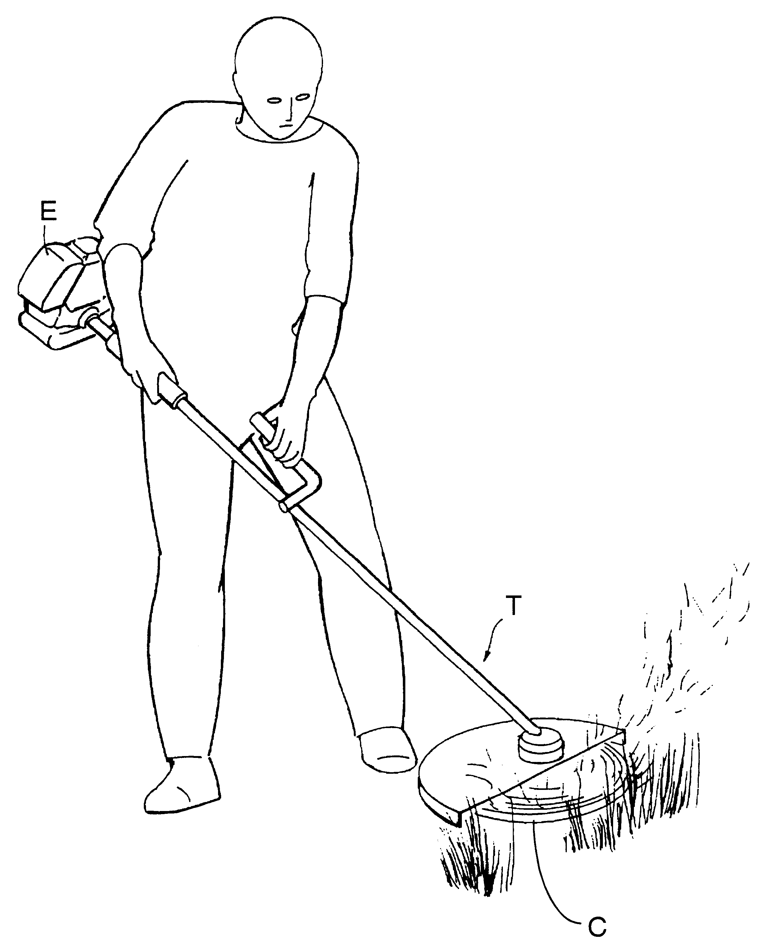
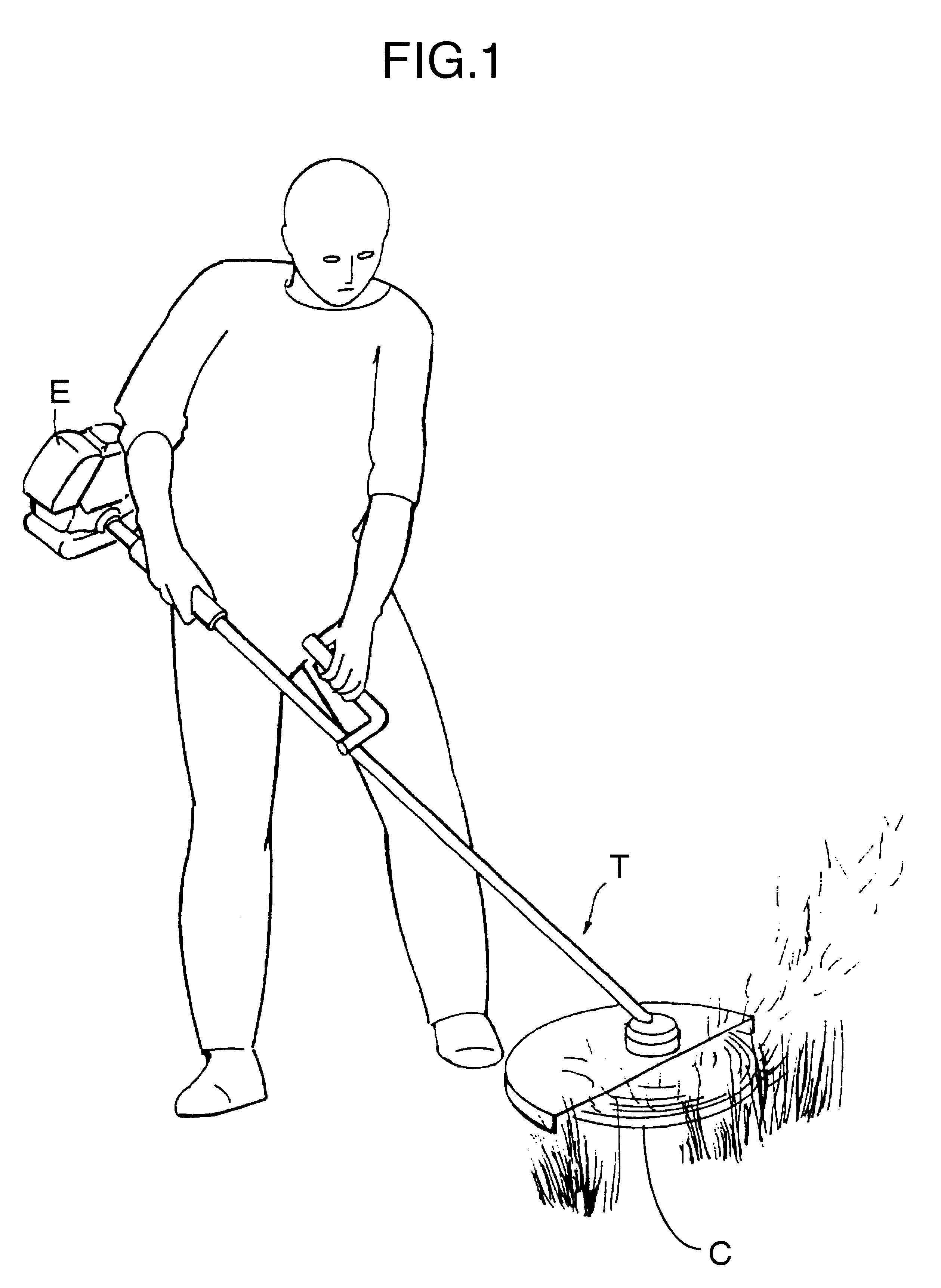
As shown in FIG. 1, a handheld type four-cycle engine E to which the present invention is applied is fitted as the source of power to the driving section of, for example, a powered trimmer T. Since the powered trimmer T is used in a manner in which a cutter C is positioned in various directions according to the operational conditions, the engine E is also tilted to a large extent or turned upside-down as a result, and the operational position is unstable.

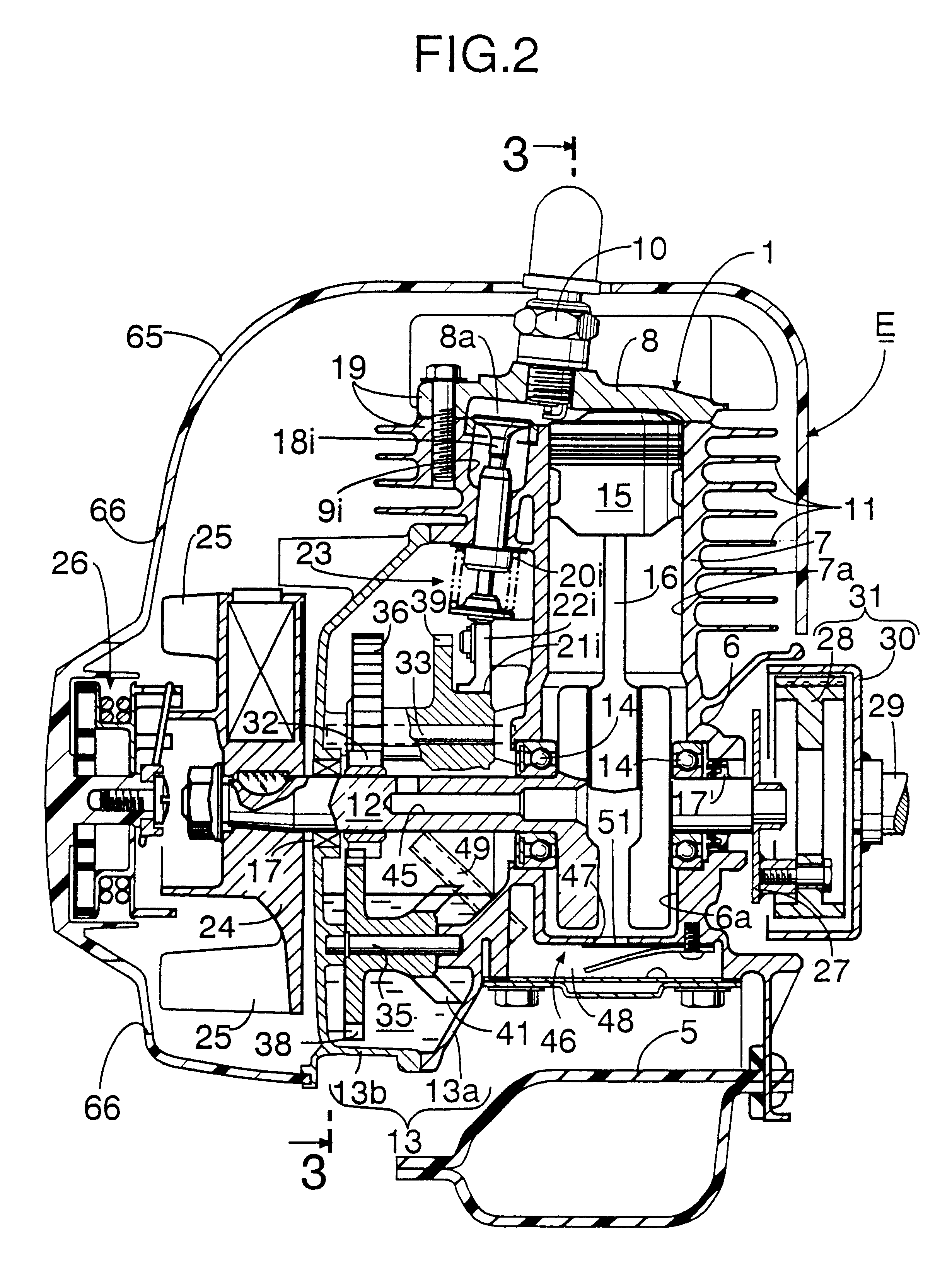
As shown in FIGS. 2 and 3, the engine main body 1 of the above-mentioned handheld type four-cycle engine E includes a crankcase 6 having a crank chamber 6a, a cylinder block 7 having one cylinder bore 7a, and a cylinder head 8 having a combustion chamber 8a, and a large number of cooling fins 11 are formed on the outer peripheries of the cylinder block 7 and the cylinder head 8.

The crankshaft 12 housed in the crank chamber 6a is supported in right and left side walls of the crankcase 6 in a rotatable manner via ball bearings 14 and ...


PUM


Abstract

With regard to a handheld type four-cycle engine including, in a side wall of a cylinder block, an intake valve, an exhaust valve and a valve operation mechanism operable in association with a crankshaft so as to open and close the above-mentioned valves and, an oil tank is formed in one side wall of the cylinder block, and the oil tank houses the valve operation mechanism and oil mist generation means for generating an oil mist from stored oil. It is thus possible to reliably lubricate the valve operation mechanism regardless of the operational position of the engine while allowing the size and weight of the engine main body to be reduced.

Description

1. Field of the InventionThe present invention relates to improvement of handheld type four-cycle engines which can desirably be used mainly as a power source for machines for portable operation such as trimmers.2. Description of the Relevant ArtWith regard to conventional handheld type four-cycle engines, one in which an oil mist generated from the oil stored in an oil reservoir is circulated inside the engine in order to lubricate the inside of the engine regardless of the operational position of the engine is already known in Japanese Patent Application Laid-open No. 10-288019.However, the lubrication system disclosed in the above-mentioned patent publication has a comparatively long and complicated circulation route in which the oil mist is circulated from the oil tank to the crank chamber, then to the valve operation chamber and is then returned to the oil tank. Such a long and complicated circulation route for the oil mist causes an increase in the size of the engine main body...

Claims


Application Information

Patent Timeline
Patent Type & Authority Patents(United States)
IPC IPC(8): F01M11/00F01M9/00F01M9/06F02B75/16F01M11/06F02B75/00F02F1/00F01M1/04F01M1/00F02B63/02F02B67/06F02F1/02F02F1/06F02F1/26F02B63/00F02F1/30F02B75/02F01L1/02F01M1/06F01M1/16F01M9/10F01M13/04
CPCF01M1/04F01M9/06F01M11/065F02B63/02F02B67/06F02B75/16F02F1/002F02F1/06F02F1/305F02B2075/027F02B2275/22F02B2275/30F02B2275/34
Inventor ITO, KEITANISHIDA, TAKAOWATANABE, SEI
Owner HONDA MOTOR CO LTD
Why Eureka
Try Eureka