
Apparatus and method for combining multiple laser beams in laser material processing systems

Inactive Publication Date: 2002-07-23
UNIVERSAL LASER SYST
View PDF27 Cites 51 Cited by
  • Summary
  • Abstract
  • Description
  • Claims
  • Application Information

AI Technical Summary

Benefits of technology

The advantages of the invention include the following: 1. Because the combiner optical elements are separately mounted on a laser material processing platform with a beam delivery system with which the outputs of the multiple lasers cooperate, the ability to use a laser to perform a broad spectrum of useful functions in a precision manner on a wide variety of materials is substantially enhanced. 2. Any laser system can be rapidly reconfigured in the field to mix power levels of various laser sources to match a particular application without the need for further alignment. 3. More efficient use of invested capital. Buy only the lase

Problems solved by technology

Any one electronic or laser tube failure will only affect that section, leaving the second channel unaffected and available for temporary use.
There are several problems with the Synrad 2-in-1 concept: 1. If one tube fails, the whole dual laser assembly must be replaced.
There is no ability to reconfigure the laser system in the field to mix power levels of various laser sources to match a particular application.
There are several problems with the Morrow apparatus.
2. While Morrow's independent mounting on a base plate of the lasers allows him some flexibility in substituting lasers, nevertheless, as in Synrad's case, because the laser beams are not pre-aligned to a predetermined reference, Morrow's dual laser source structure cannot be rapidly reconfigured in the field to mix power levels of various laser sources to match a particular application without the need for a further alignment procedure.

Method used


Image

  • Apparatus and method for combining multiple laser beams in laser material processing systems
  • Apparatus and method for combining multiple laser beams in laser material processing systems
  • Apparatus and method for combining multiple laser beams in laser material processing systems

Examples


Embodiment Construction

In order to simplify the explanation of the present invention, the following discussion describes the present invention in terms of the two laser sources shown in FIGS. 1-3. However, those of ordinary skill in the art will understand from this disclosure that an infinite number of laser sources may be used in the configurations disclosed herein. Accordingly, it is the intention of the applicants that the scope of the invention be interpreted to include structures having such a plurality of laser sources.

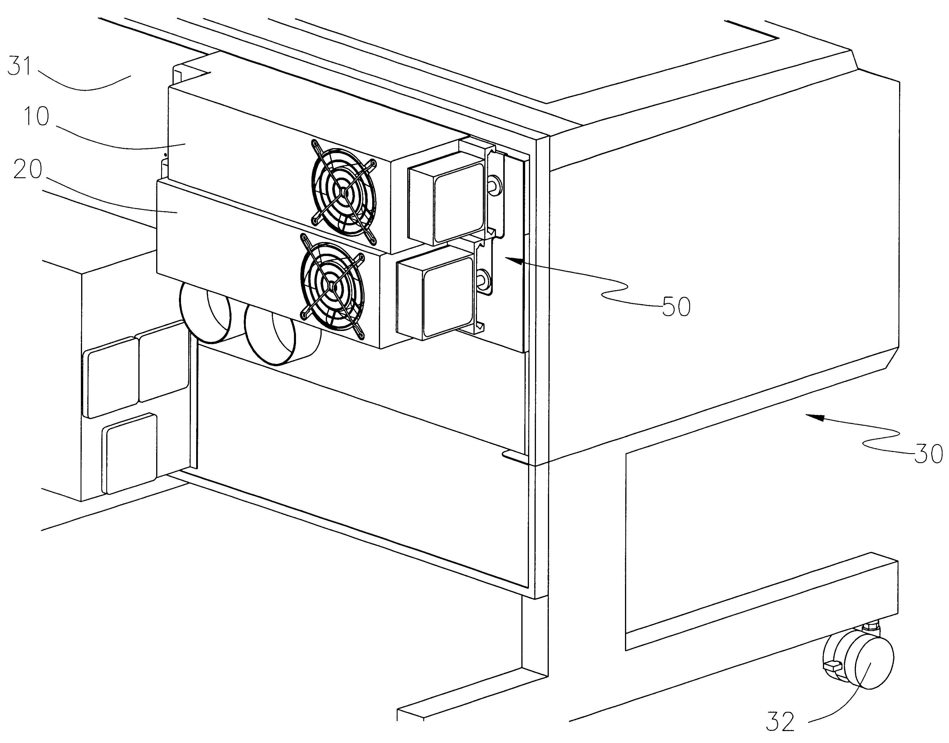
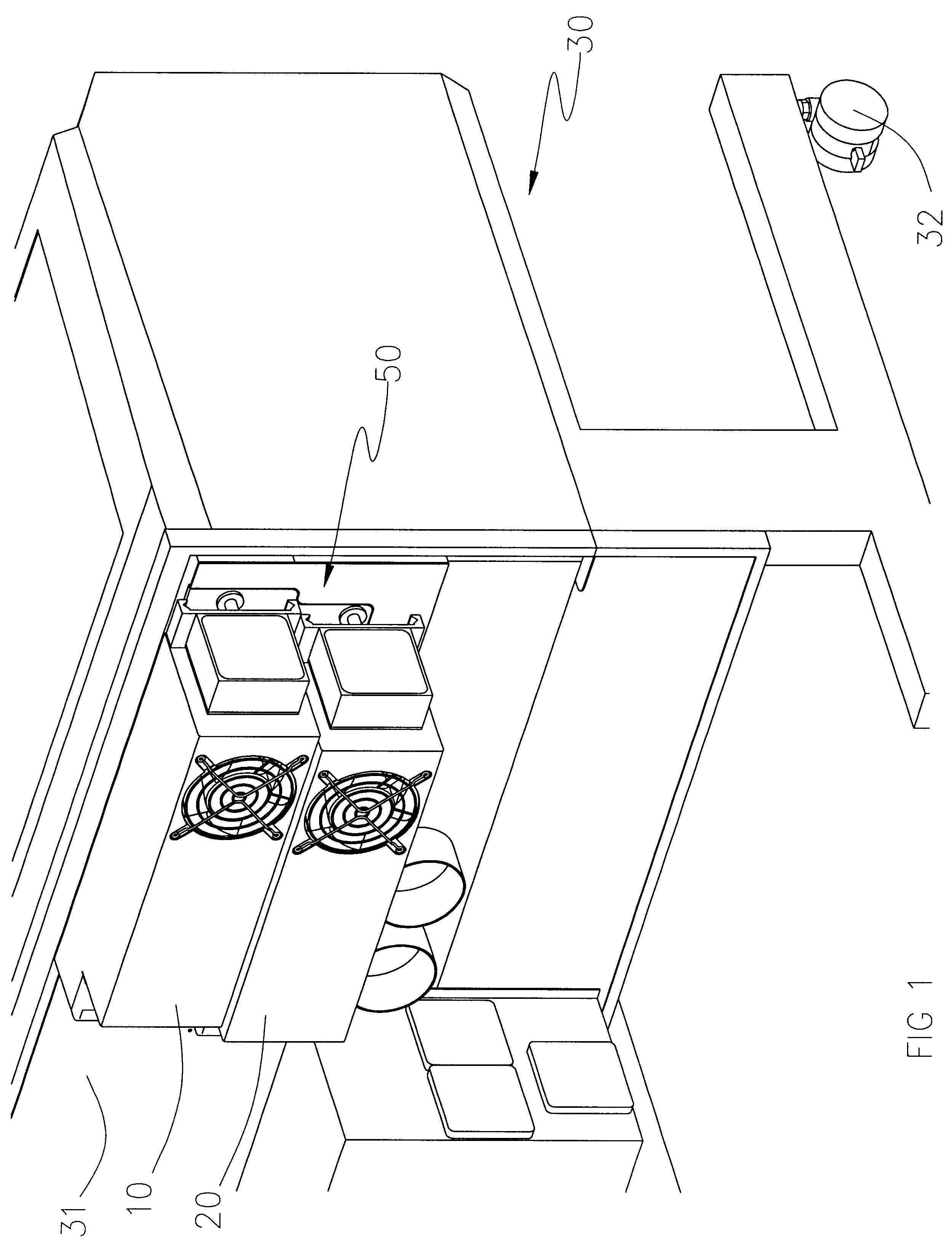
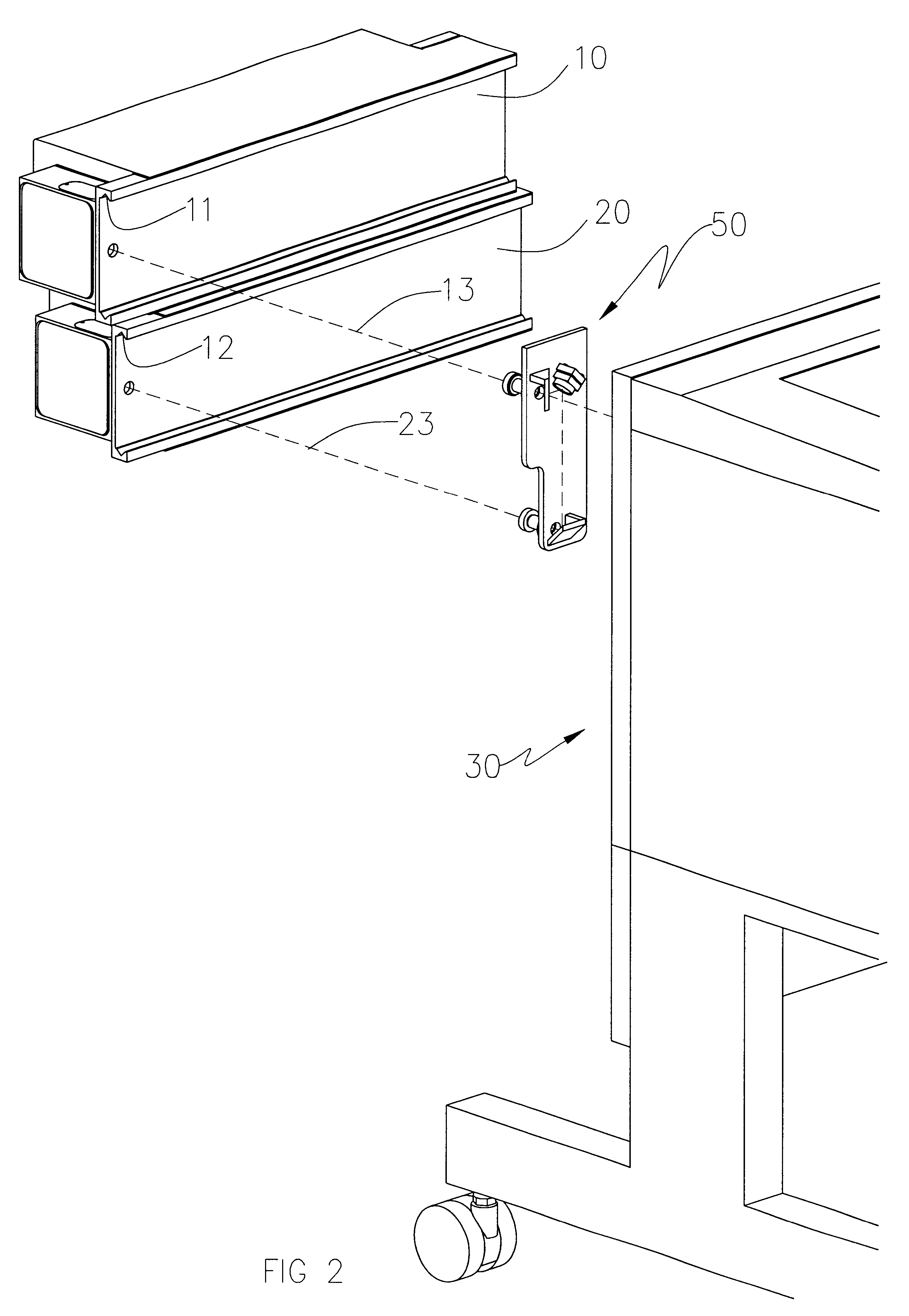
As seen in FIGS. 1-3 two laser sources 10, 20 are each separately mounted on separate mounting members (not shown) affixed to the back mounting plate 31 of mobile 32 laser material processing platform 30 wherein downturned V-grooves 11,12 of laser sources 10, 20 respectively receive upturned ridges (not shown) of the mounting members (not shown)in accordance with the pre-alignment procedure taught in our co-pending application referenced above. Additionally, the beam paths 13, 23 of ...


PUM

PropertyMeasurementUnit
Angleaaaaaaaaaa

Abstract

Each one of multiple laser sources are independently separately mounted on a laser material processing platform and their beam paths are combined by a combiner which includes one or more optical elements mounted in the laser material processing platform which make the beam paths parallel and colinear. The combined beams are then moved in X and Y planes relative to a workpiece supported in the laser material processing platform under the control of a computer in the performance of work in accordance with a work program. The beam path of each laser source and the optical axis of the beam delivery system are each pre-aligned to the same predetermined reference and automatically coincide upon installation such that these components are rapidly and interchangeably interfaceable. The beams are orthogonally polarized and the optical elements of the combiner transmit one beam while reflecting another beam. While two laser beams are shown, an infinite number of laser beams may be used.

Description

CROSS-REFERENCES TO RELATED APPLICATIONSNot ApplicableSTATEMENT REGARDING FEDERALLY SPONSORED RESEARCH AND DEVELOPMENTNot ApplicableBACKGROUND OF THE INVENTION1. Fields of the InventionThe present invention relates generally to apparatuses and methods of combining the multiple laser beams of multiple laser sources wherein the beam combiner is mounted in a laser material processing platform, and, more particularly, to combining pre-aligned multiple laser beams of multiple laser sources each of which is independently interfaced with a pre-aligned optical axis of a beam delivery system of the laser material processing platform.2. Discussion of Background and Prior Arta. Widespread Applications And Rapid Growth Of Laser Material Processing Systems Mandated Interchangeability and Interfaceability of Laser System ComponentsIn our co-pending application entitled Method And Apparatus For Making Laser Sources and Laser Platforms Interchangeable and Interfaceable, which is hereby incorporated...

Claims


Application Information

Patent Timeline
IPC IPC(8): B23K26/06H01S5/40H01S3/23H01S3/00H01S5/00
CPCB23K26/0604B23K26/0613H01S3/005H01S3/2383H01S5/005H01S5/4025
Inventor SUKHMAN, YEFIM P.RISSER, CHRISTIAN J.GORHAM, EDWIN W.
Owner UNIVERSAL LASER SYST
Learn More