Method and device to measure the temperature of microwave components

a technology of microwave components and measuring devices, which is applied in the direction of instruments, heat measurement, material heat development, etc., can solve the problem of insufficient control of pulsed operation

Inactive Publication Date: 2002-08-13
THOMSON CSF SA
View PDF3 Cites 10 Cited by
  • Summary
  • Abstract
  • Description
  • Claims
  • Application Information

AI Technical Summary

Problems solved by technology

While this feature is valuable for knowing the junction temperature in CW mode, it proves to be insuffici...

Method used


Image

  • Method and device to measure the temperature of microwave components
  • Method and device to measure the temperature of microwave components
  • Method and device to measure the temperature of microwave components

Examples


Embodiment Construction

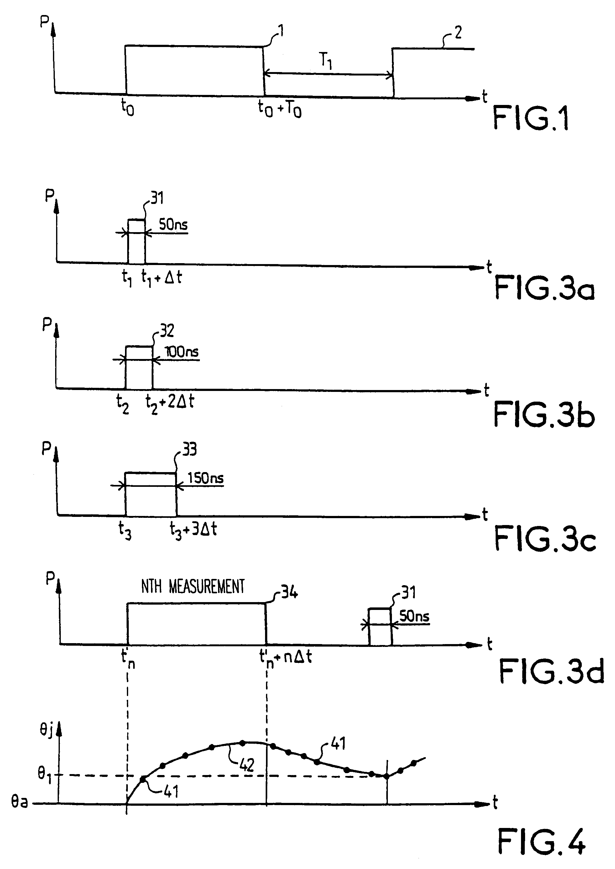
FIG. 1 illustrates a train of chopped microwave pulses with a first pulse 1 and the start of a second pulse 2 in an axial system where the y-axis represents the microwave power P arriving at a component being tested and the x-axis represents the time t. The first pulse 1 starts at a time t0and ends at a later time t0+T0. These two nominal pulses are for example representative of a radar operation mode. They actually represent the conditions in which the component will progress. In particular, the power P of an incident pulse represents a state of instantaneous operation of the component.

According to the invention, a sequence of microwave signal pulses of growing length and preferably constant power are sent to the component at least until the duration of the last pulse reaches the duration T0of the nominal pulse 1. The duration of the last pulse may be equal for example to this duration T0. These test pulses increase, for example, evenly, i.e. according to a step with a constant dur...


PUM


Abstract

In a method and a device for the measurement of the mean temperature of components, a sequence of test pulses of increasing duration is applied to the component, the power of the pulses representing a state of operation of the component, a measurement of junction temperature being performed at the end of each pulse to obtain a curve representing the progress of the junction temperature of the component as a function of time on the basis of the temperature measurement points obtained at the end of each pulse. The disclosed method and device can be applied especially to determine the junction temperature of microwave electronic components working in continuous mode or in pulsed mode.

Description

1. Field of the InventionThe present invention relates to a method and a device to measure the mean temperature of components. It can be applied especially to the determining of the junction temperature of microwave electronic components working in continuous wave (CW) mode or in pulse mode.2. Description of the Prior ArtRadar techniques use, in particular, microwave circuits capable of conveying high power values, such as phase-shifters, limiters or, again, power amplifiers. These amplifiers, which are sometimes called"solid-state" amplifiers, use especially semiconductor-based microwave components such as, for example, class C biased power bipolar transistors. However, the limiters and the phase-shifters most commonly use diodes and, especially, PIN diodes. These different components generally work in radar mode, namely in pulsed operation. In this working mode, the wave is sent by the radar in the form of pulses whose length and repetition period may be fixed or variable in time....

Claims


Application Information

Patent Timeline
IPC IPC(8): G01R19/25G01R31/26G01K7/01
CPCG01R19/25G01R31/2619G01R31/2628G01R31/2632
Inventor TOLANT, CLEMENTCORDIER, JOELEUDELINE, PHILIPPESERVAIN, PATRICK
Owner THOMSON CSF SA
Why Eureka
Try Eureka