Method for making shallow trenches for isolation

a technology of isolation trenches and shallow trenches, which is applied in the direction of basic electric elements, electrical equipment, and semiconductor devices, can solve the problems of reducing the efficiency of isolation structures, mechanical stress and dislocation of isolation dielectrics, and not being compatible with the thermal budget of some fabrication processes, so as to reduce mechanical stresses

Inactive Publication Date: 2002-08-20
APTINA IMAGING CORP
View PDF15 Cites 92 Cited by
  • Summary
  • Abstract
  • Description
  • Claims
  • Application Information

AI Technical Summary

Benefits of technology

The present invention provides an improved method for creating shallow trench isolation structures. In one embodiment, a patterned mask is formed on a semiconductor substrate. The substrate is then subjected to dopant implantation to form highly doped regions in the non-masked portions of the substrate. After implantation, the highly doped regions are first anodized and then oxidized, leading to the formation of a porous oxide. This porous oxide is removed by a wet etching process, leaving behind a trench with exposed silicon. The trench is then oxidized and filled with a conventional suitable dielectric. The process produces a shallow trench with rounded corners which reduces mechanical stresses at the isolation region boundaries.

Problems solved by technology

One problem arises due to stress in the bottom of the trench.
The rectangular corners formed at the bottom of STI trenches fabricated by traditional methods can lead to stress and dislocations in the isolation dielectric.
This can further lead to current leakage paths and contaminants, which in turn reduce the effectiveness of the isolation structure.
U.S. Pat. No. 5,956,598 provides a method for rounding the corners of STI structures, but the method described in this reference requires a high temperature anneal, which may not be compatible with the thermal budget of some fabrication processes.
Depth control of the isolation trench poses another problem.
As a result, dry etch processes, which have tolerable process variations for deeper trenches, become increasingly less acceptable for shallower trench structures.
A further limitation of the current art stems from the photolithography techniques.

Method used


Image

  • Method for making shallow trenches for isolation
  • Method for making shallow trenches for isolation
  • Method for making shallow trenches for isolation

Examples


second embodiment

The masking and implant steps of the above embodiment provide for a trench with a generally rectangular shape, but with considerably rounded corners within the substrate. In the embodiments that will be described in more details bellow, the masking and implant steps may be selected to provide for a trench with a tiered structure (such as trench 32 of FIGS. 15, 16) or for a trench with a light-bulb shape (such as structure 58 of FIG. 18). The tiered structure of the second embodiment will now be described in more detail bellow, with reference to FIGS. 7-16.

FIG. 7 depicts a portion of a representative substrate 20 processed according to a second embodiment of the present invention, to form tiered STI structure 34 (FIGS. 15, 16). As shown in FIG. 7, a first implantation mask 24 has already been deposited on the surface of substrate 20. The first implantation mask 24 is a hard masking layer, such as a silicon oxide or silicon nitride. An opening 26 is formed in the first implantation ma...

first embodiment

Once heavily doped region 29 has been created with the tiered structure shown in FIG. 11, the remainder of the invention may be carried out in a manner similar to the first embodiment detailed above. Accordingly, the implantation mask 24 and spacers 27 are removed from the substrate 20 to form the structure of FIG. 12, by using removal processes that vary according to the nature of the mask 24 and oxide 25. For example, oxygen ashing followed by a residual cleaning step may be employed for a photoresist mask. Similarly, treating the substrate with hot H.sub.3 PO.sub.4 is employed for a Si.sub.3 N.sub.4 mask.

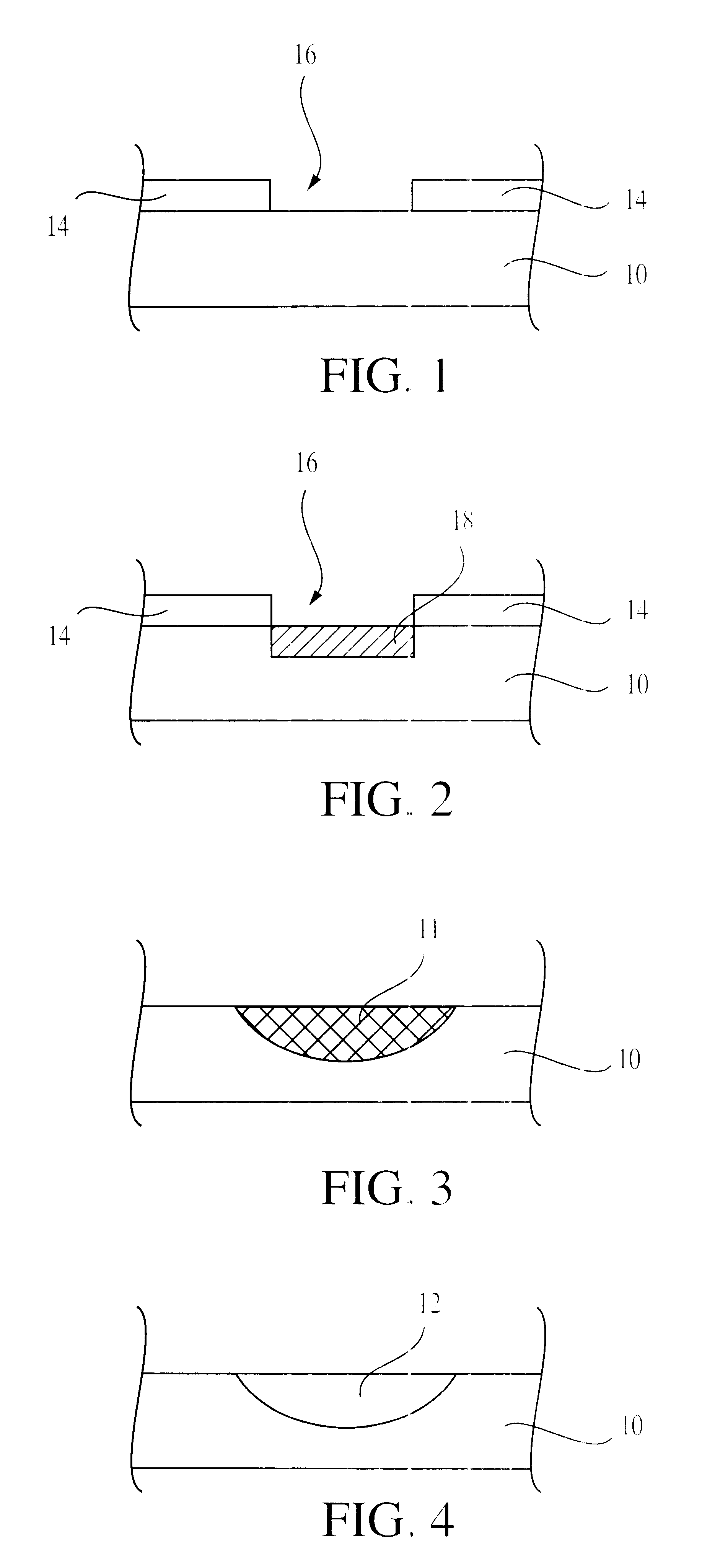
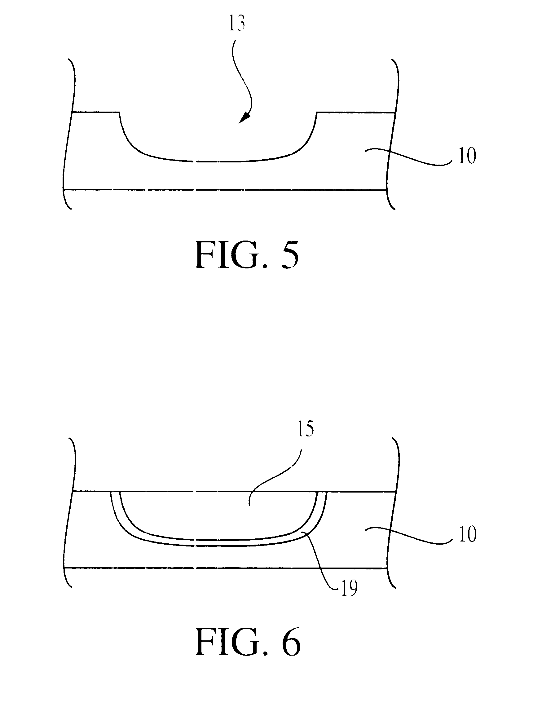
The heavily doped regions 29a,b are anodized to form a porous silicon region 30 (FIG. 13). The porous silicon region 30 is then oxidized to form oxidized silicon region 31 (FIG. 14). The anodization and oxidation steps of the second embodiment may be carried out in a way similar to that described for the first embodiment and with reference to FIGS. 3-4. Next, the oxidized porous ...

third embodiment

The third embodiment allows for formation of isolation trenches that are narrower than the critical dimension of the available lithographic methods. This is accomplished by patterning the mask 44 to provide the narrowest possible opening 46 for the available lithography technology. After creating the opening 46, spacers 47 are formed within the opening 46, and thus an opening that may be narrower than the critical dimension of the lithography technique could be attained. After the formation of spacers 47, the substrate 40 is subjected to a dopant implantation. The reduced width of opening 46 will result in a reduced width of heavily doped region 48 (FIG. 17), and, accordingly, to a narrower isolation trench. As in the first embodiment, the heavily doped region 48 is anodized to form a porous silicon. The porous silicon is then oxidized and removed, preferably by wet etching, leaving behind a trench for the shallow trench isolation structure. An insulating layer may be optionally for...


PUM


Abstract

An improved method for forming shallow trench isolation structures having reduced stress and allowing for greater control over shape, size and characteristics of the shallow trench isolation structures is disclosed. The isolation trench is defined by implanting a substrate through a patterned mask to create heavily doped regions. These heavily doped regions are anodized to form porous silicon and then oxidized. The oxidized porous silicon is removed, leaving behind a trench having rounded corners which is filled with an isolation dielectric.

Description

FIELD OF THE INVENTIONThe present invention relates to the field of semiconductor integrated circuits and, in particular, to an improved structure and method for making shallow trenches for isolation.BACKGROUND OF THE INVENTIONShallow trench isolation (STI) is an essential part of current fabrication methods for microelectronic circuits. The decreasing dimensions of devices and the increasing density of integration in microelectronic circuits have required a corresponding reduction in the size of isolation structures. This reduction places a premium on reproducible formation of structures which provide effective isolation, while occupying a minimum amount of the substrate surface.The STI technique is a widely used semiconductor fabrication method for forming isolation structures to electrically isolate the various active components formed in integrated circuits. In the STI technique, the first step is the formation of a plurality of trenches at predefined locations in the substrate,...

Claims


Application Information

Patent Timeline
Patent Type & Authority Patents(United States)
IPC IPC(8): H01L21/762H01L21/70
CPCH01L21/76235
Inventor GILTON, TERRY L.
Owner APTINA IMAGING CORP
Why Eureka
Try Eureka