Near field optical scanning system employing microfabricated solid immersion lens

a technology of optical scanning and solid immersion lens, applied in the field of optical scanning system, can solve the problems of difficult integration into arrays, unsuitable for high-speed lithography, scanned imaging, microscopy or optical storage, and poor efficiency of tapered optical fiber probes

Inactive Publication Date: 2002-08-27
THE BOARD OF TRUSTEES OF THE LELAND STANFORD JUNIOR UNIV
View PDF17 Cites 164 Cited by
  • Summary
  • Abstract
  • Description
  • Claims
  • Application Information

AI Technical Summary

Problems solved by technology

Thus, tapered optical fiber probes typically have very poor efficiency, making them unsuitable for high speed lithography, scanned imaging, microscopy or optical storage.
Furthermore, the probes are usually manufactured singly and are difficult to integrate into arrays, which prevents their use for parallel imaging, lithography or optical storage.

Method used


Image

  • Near field optical scanning system employing microfabricated solid immersion lens
  • Near field optical scanning system employing microfabricated solid immersion lens
  • Near field optical scanning system employing microfabricated solid immersion lens

Examples


Embodiment Construction

)

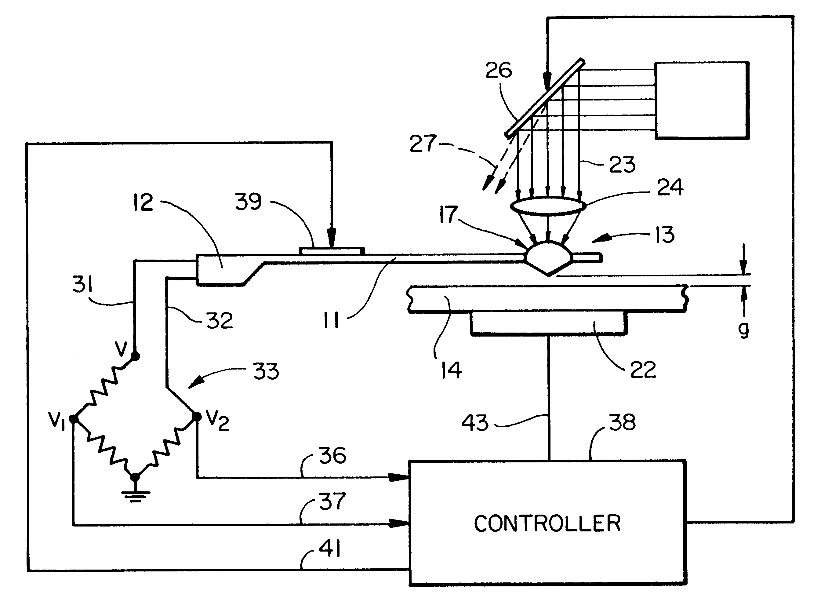
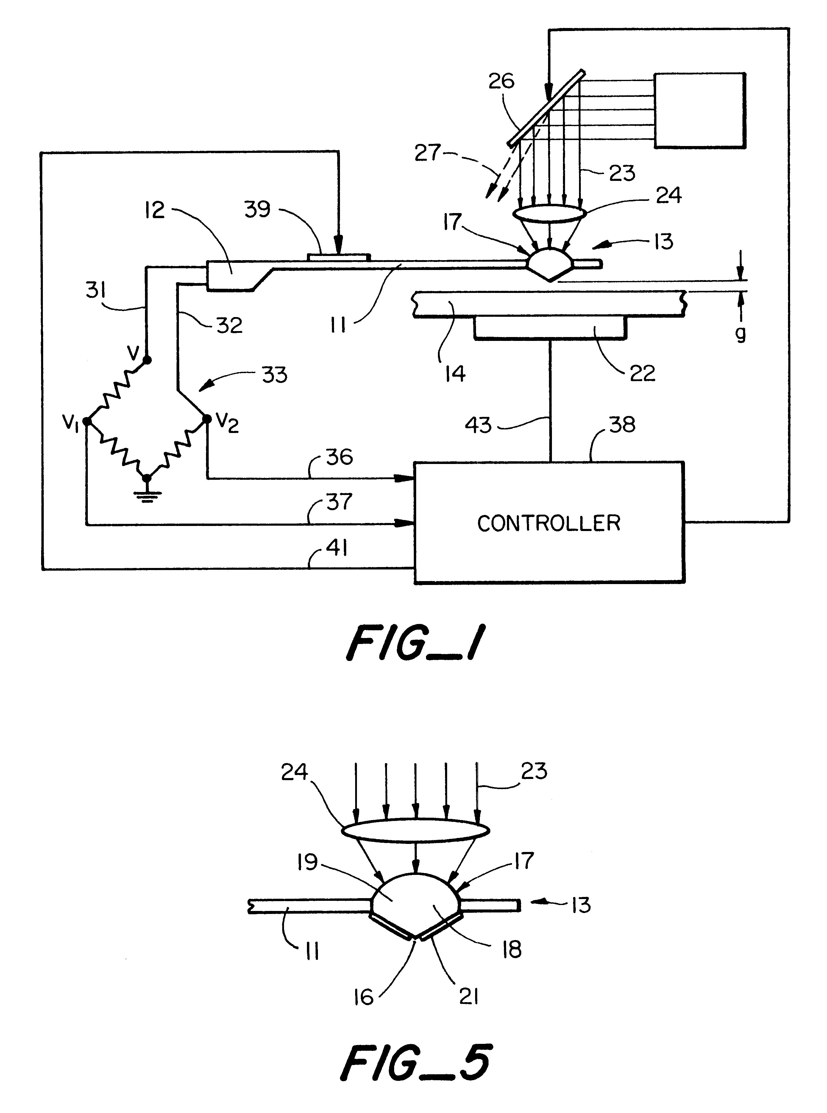
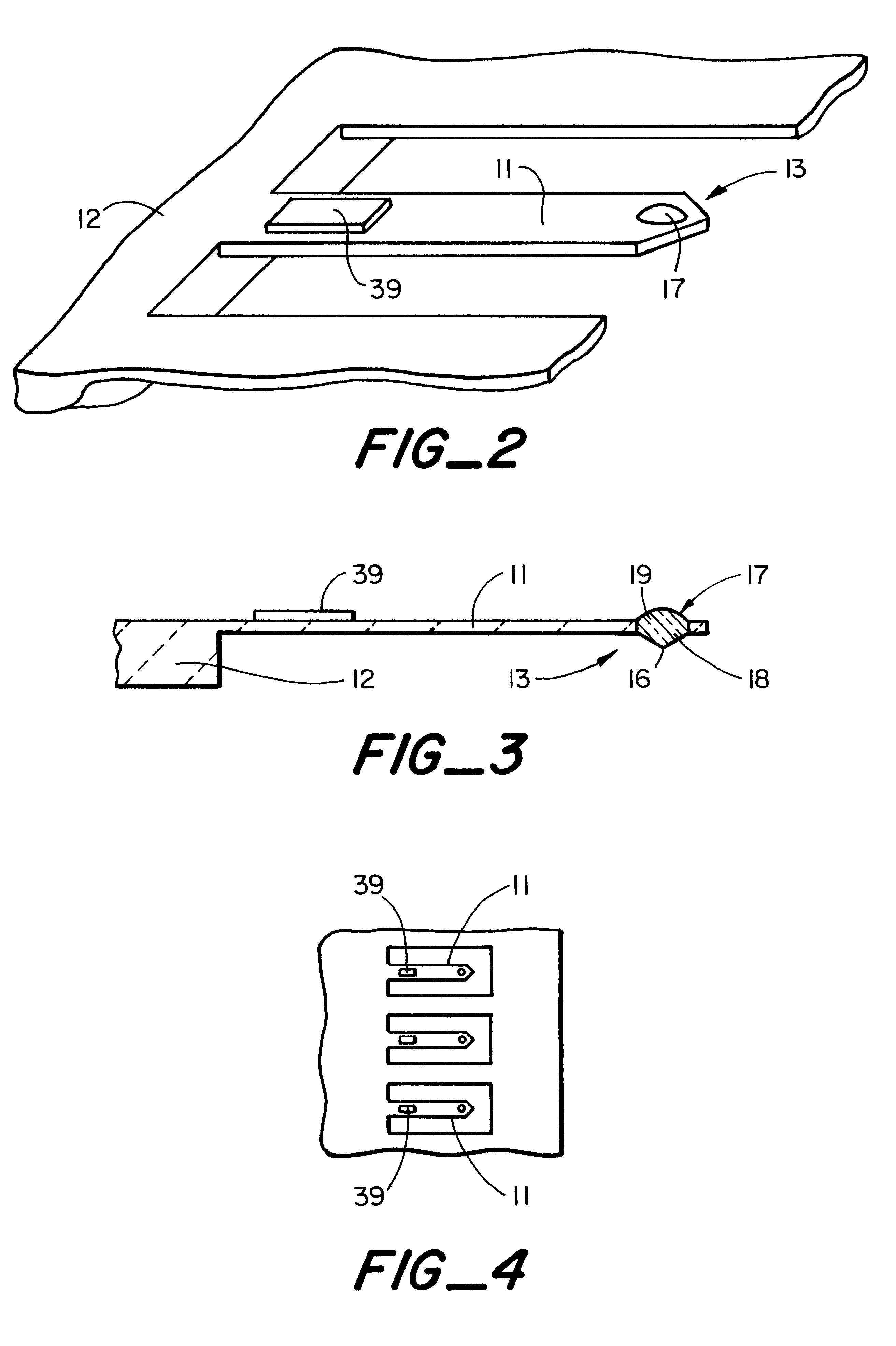
It will become apparent that the micromachined solid immersion lens and cantilever support of the present invention are useful in photolithography systems, optical scanning microscope systems, magneto-optic information storage and retrieval systems, etc. To better appreciate the invention, a lithography system employing the invention is first generally described. The system includes an array of cantilevers with each cantilever in the array having a tip integrated into the end of the cantilever which is typically made of the same material as the cantilever, such as silicon for infrared use or SiN for use in the ultraviolet or optical range. The tip includes a solid immersion lens and preferably a tip such as a pyramidical or conical tip. During the exposure process, the tip is maintained close to the substrate. The tip to sample distance is controlled by an optical lever deflection system. During exposure the sample is scanned by a scanning stage, and the light intensity at each len...


PUM

PropertyMeasurementUnit
diameteraaaaaaaaaa
diameteraaaaaaaaaa
refractive indexaaaaaaaaaa

Abstract

A solid immersion lens integrated on a flexible support such as a cantilever or membrane is described, together with a method of forming the integrated structure.

Description

This invention relates generally to a scanning system employing near field optics, and more particularly to a system which includes solid immersion lenses mounted on cantilevers and to methods of fabricating the cantilevers with integral solid immersion lens.Near field optical scanning has in recent years been applied to optical imaging, magneto-optic (MO) storage and lithography. In near field optical scanning, light pixels of sub-wavelength dimensions are achieved by scanning an aperture of sub-wavelength dimensions or by scanning a solid immersion lens very close to a sample.A photolithography system employing near field optics is described in U.S. Pat. No. 5,517,280 which is incorporated herein in its entirety by reference. The photolithography system described in the '280 patent includes an array of cantilevers, preferably formed in a silicon wafer. Each cantilever includes a transparent pyramidical or conical tip located near the free end of the cantilever.The array of cantile...

Claims


Application Information

Patent Timeline
Patent Type & Authority Patents(United States)
IPC IPC(8): G03F7/20G12B21/00G12B21/06G01Q10/00G01Q60/18G01Q60/22G11B7/135G11B11/105
CPCB82Y20/00B82Y35/00G01Q60/22G03F7/70325G03F7/70825G11B7/1374G11B7/1387B82Y10/00G11B11/10534Y10S977/862
Inventor COZIER, KENNETH B.FLETCHER, DANIEL A.KINO, GORDON S.QUATE, CALVIN F.SOH, HYONGSOK T.
Owner THE BOARD OF TRUSTEES OF THE LELAND STANFORD JUNIOR UNIV
Why Eureka
Try Eureka