Method and apparatus for determining transit-time differentials for signal waveforms for real-time pattern recognition, localization and monitoring of optical and acoustic signals

a signal waveform and transit time differential technology, applied in direction finders using ultrasonic/sonic/infrasonic waves, amplifiers, transmission, etc., can solve the drawback of multi-template matching procedures, parallel, multi-template matching procedures, and invariant translation, so as to increase the accuracy of measurement

Inactive Publication Date: 2002-08-27
KLEFENZ FRANK
View PDF1 Cites 32 Cited by
  • Summary
  • Abstract
  • Description
  • Claims
  • Application Information

AI Technical Summary

Benefits of technology

The objective of the invention is to create a method and apparatus to segment-wise detect and bring into coincidence signal waveforms which can be converted into monotone and continuous trajectories, in particular to recognize patterns in real time, to localize and to monitor optical and acoustic signals, and to determine transit differentials with increased accuracy of measurement by making it possible to program the key waveforms and the resolution.

Problems solved by technology

The conventional template-matching procedures incur the drawback that they fail to be invariant in the presence of spatial shifts.
The known translationally invariant, parallel, multi-template matching procedures used to determine the transit-time differential of acoustic signals incur the drawback of the complex simulation of a biological cochlea, in particular in tuning the response of the cochlea to different energizing signals by varying the relevant parameters describing the cochlea.
Another drawback resulting from the circuitry of the heretofore designed analog configurations is the adjustment, subject to manufacturing tolerances, of the delay speeds in the analog delay lines subject.
The heretofore predominantly employed digital signal processors (DSP's) incur a drawback in that they do not properly match the present problem's solution contained in the method and apparatus of the invention.
A DSP is incapable of solving said problem of a defined magnitude within an adequately short time, and in many cases such inability may entail problems.
A further general drawback of the DSP's prevailingly used to-date for signal processing and pattern recognition is that the procedure and the apparatus poorly match the above solution to the problem addressed herein.
Another general drawback of the DSP's is the central control unit and the scarcity of computers able to process the data flows in the manner of the method and apparatus of the present invention.
Because of its fixed CPU architecture, a digital signal processor is unable to simulate the apparatus'signal-flow architecture at which the signal flows pass in time though said apparatus.

Method used


Image

  • Method and apparatus for determining transit-time differentials for signal waveforms for real-time pattern recognition, localization and monitoring of optical and acoustic signals
  • Method and apparatus for determining transit-time differentials for signal waveforms for real-time pattern recognition, localization and monitoring of optical and acoustic signals
  • Method and apparatus for determining transit-time differentials for signal waveforms for real-time pattern recognition, localization and monitoring of optical and acoustic signals

Examples


Embodiment Construction

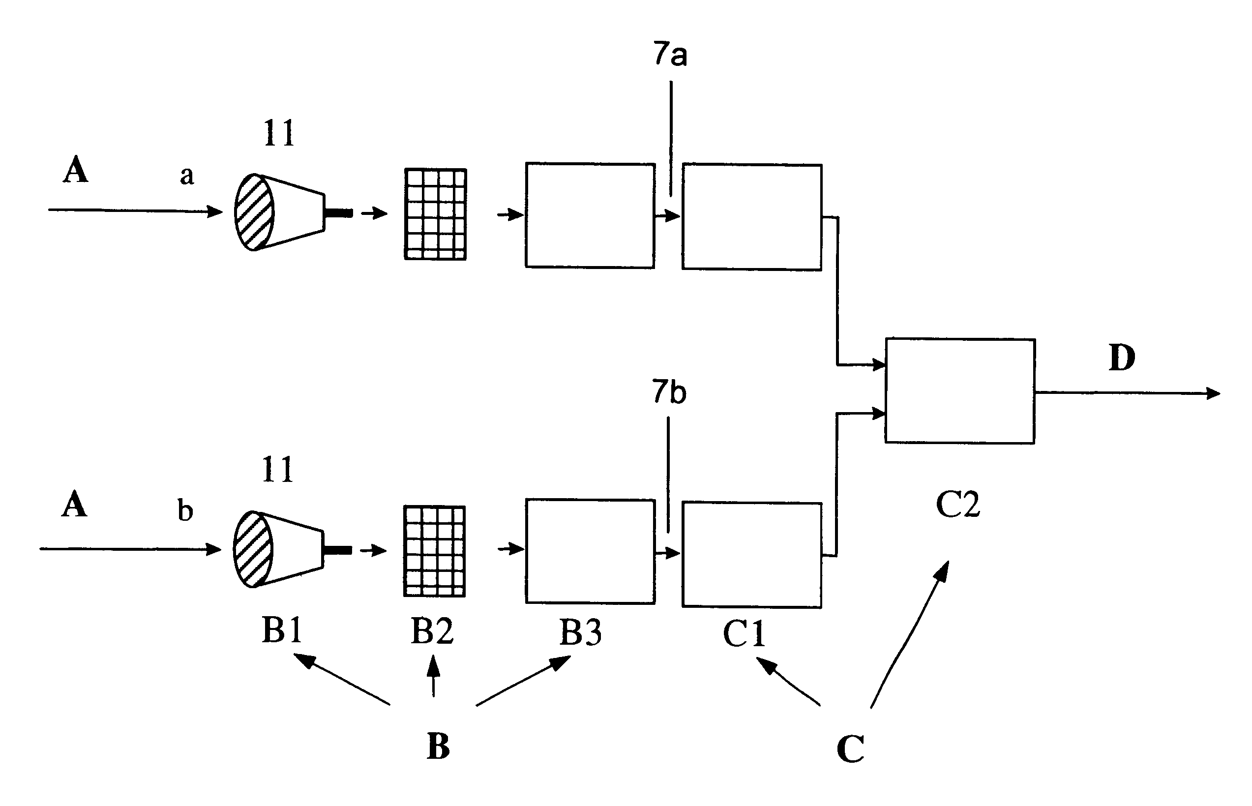
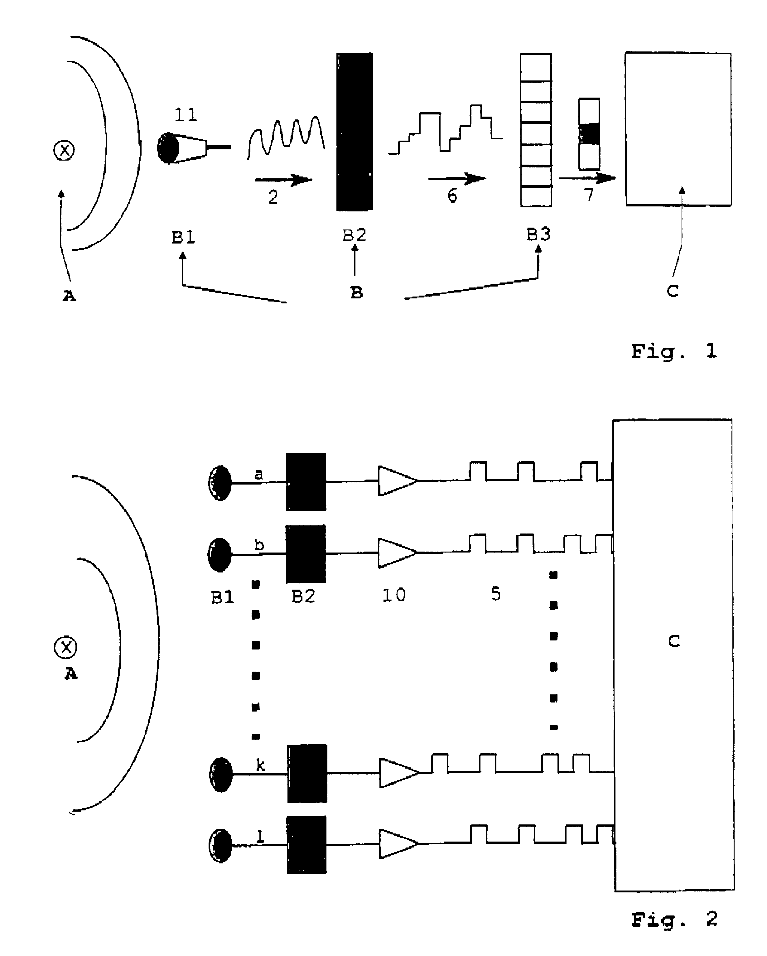
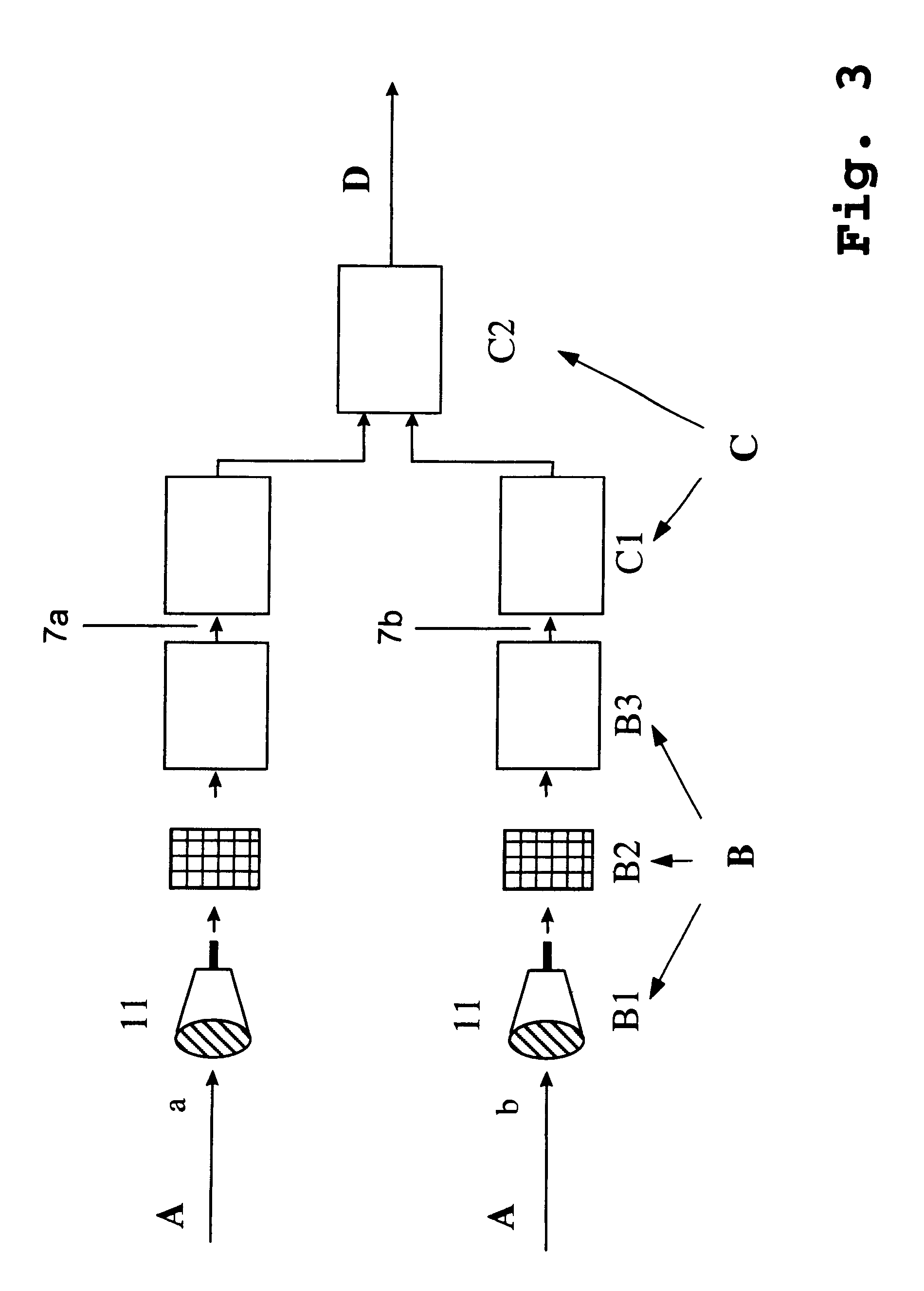
In the method of the invention, first pattern recognition is carried out and then the determination of the transit-time differential by detecting key waveforms, and the information is processed further in a subsequent multi-coincidence unit; shift-invariant, parallel multi-template matching is carried out during which key waveforms are correlated in parallel and an output per clock step, illustratively of a set of transit-time differentials, is created in the said subsequent multi-coincidence unit.

The method to segment-wise determine pattern recognition and transit-time differentials of signal waveforms which can be converted into monotone and continuous space-time trajectories, in particular for purposes of real-time pattern recognition, is characterized in that pre-programmed key signals are detected by signal sampling and processing the sampled data, further by subjecting to multiple coincidences combined signal pairs of different signal transit times and different waveforms. At ...


PUM

PropertyMeasurementUnit
transit-timeaaaaaaaaaa
speedaaaaaaaaaa
programmable threshold valueaaaaaaaaaa

Abstract

A method includes the steps of segment-wise detecting and bringing into coincidence signal waveforms for conversion into monotone and continuous trajectories for real-time pattern recognition, localization, and monitoring optical and acoustic signals. The method also determines transit-time differentials, wherein pre-programmed key signals are detected by signal sampling, data is correlated from the sampled signals, and pairs of signal combinations of given signal transit-time differentials from the coincidence of the detected signals are determined. The apparatus includes at least two receivers for generating sequences of digital values from incoming acoustic signals, vector generators to convert the digital values into input vectors (7), a signal detection unit (C1) downstream from each vector generator and having parallel, programmable signal-flow chains and adder/comparator units (1, 10) mounted perpendicularly to the signal-flow chains at equidistant spacings, and a multi-coincidence unit (C2) consisting of two antiparallel shift-register forming flipflop chains and an AND gate (20).

Description

DESCRIPTION1. State of the ArtThe invention relates to a method and apparatus to segment-wise detect and bring into coincidence signal waveforms which can be converted into monotone and continuous trajectories, in particular for purposes of real-time pattern recognition, of position finding and determination of transit-time differentials. Said signals are sample in time-discrete manner at the input side, are detected by correlation and thereupon the signal transit-times of different pairs of signal combinations and of different signal waveforms will then be determined.The invention also relates to apparatus implementing such a method.A procedure of the above kind used in signal detection is based on conventional template matching wherein the input signal is correlated with a pre-stored reference signal. By means of time-discrete sampling, the signal is rendered as a sequence of input vectors which form a matrix within which the signal is determined by the sum of all matrix pixel pos...

Claims


Application Information

Patent Timeline
Patent Type & Authority Patents(United States)
IPC IPC(8): G01H3/00G01H5/00G01V1/00G01S5/18G01S3/46G01S3/782G01S3/808G06F17/00
CPCG01H3/00G01H5/00G01V1/001
Inventor KLEFENZ, FRANK
Owner KLEFENZ FRANK
Why Eureka
Try Eureka