Ring oscillator clock frequency measuring method, ring oscillator clock frequency measuring circuit, and microcomputer

Inactive Publication Date: 2002-08-27
MITSUBISHI ELECTRIC SYST LSI DESIGN +1
View PDF6 Cites 22 Cited by
  • Summary
  • Abstract
  • Description
  • Claims
  • Application Information

AI Technical Summary

Problems solved by technology

Thus, a conventional system requiring high frequency accuracy cannot use a ring oscillator clock si

Method used


Image

  • Ring oscillator clock frequency measuring method, ring oscillator clock frequency measuring circuit, and microcomputer
  • Ring oscillator clock frequency measuring method, ring oscillator clock frequency measuring circuit, and microcomputer
  • Ring oscillator clock frequency measuring method, ring oscillator clock frequency measuring circuit, and microcomputer

Examples


embodiment 1

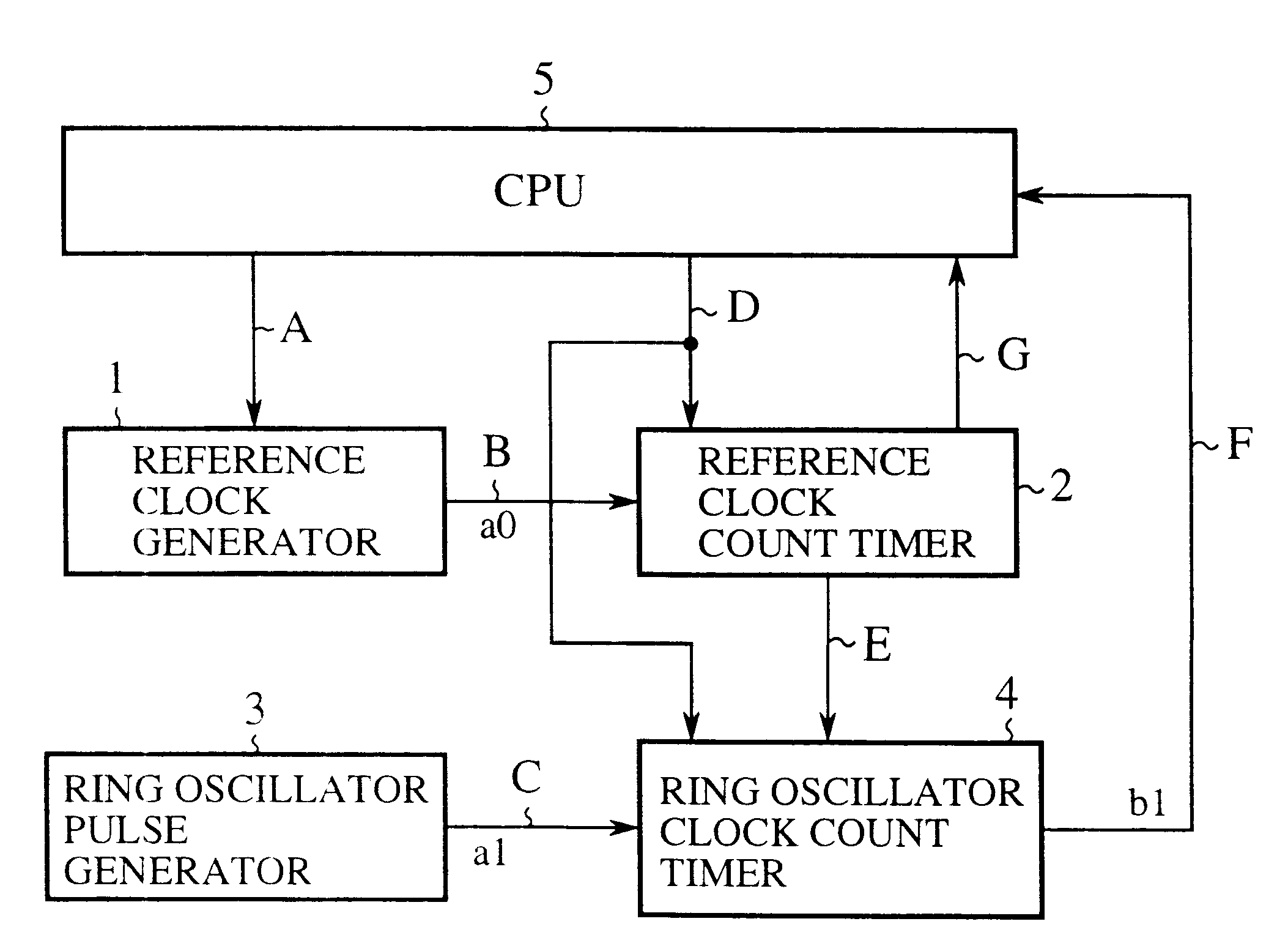
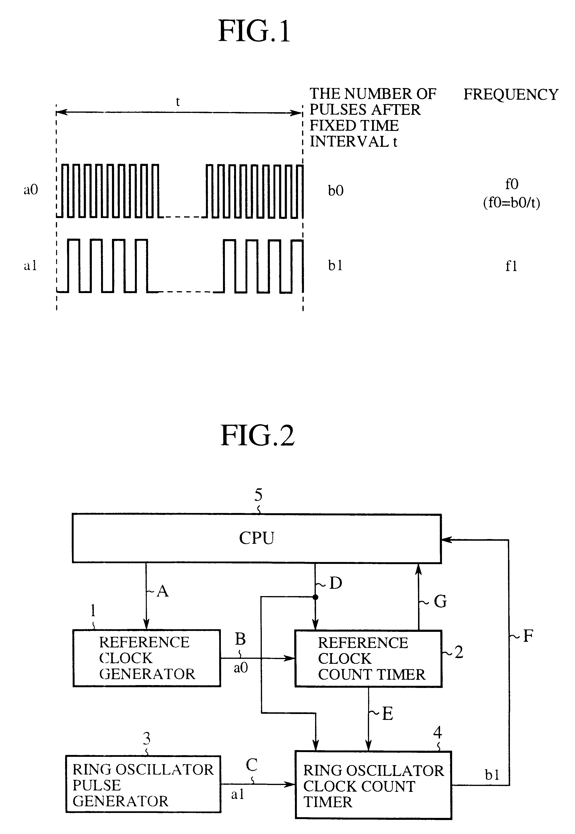
FIG. 1 illustrates a principle of the ring oscillator clock signal frequency measurement of an embodiment 1 in accordance with the present invention. In FIG. 1, the symbol a0 designates the output pulse train of an external reference clock generator, and a1 designates the output pulse train of a ring oscillator. The symbol t designates a fixed time interval in which the frequency is measured, b0 designates the number of pulses of the reference clock signal during the fixed time interval t, and b1 designates the number of pulses of the ring oscillator clock signal during the fixed time interval t. The symbol f0 designates the frequency of the reference clock signal, and f1 designates the frequency of the ring oscillator clock signal.

Here, the relationship between the reference clock signal frequency f0 and the ring oscillator clock signal frequency f1 is expressed by the following equation (1)

f1=f0.times.b1 / b0 (1)

Thus counting the number b1 of the output pulses of the ring oscillator...

embodiment 2

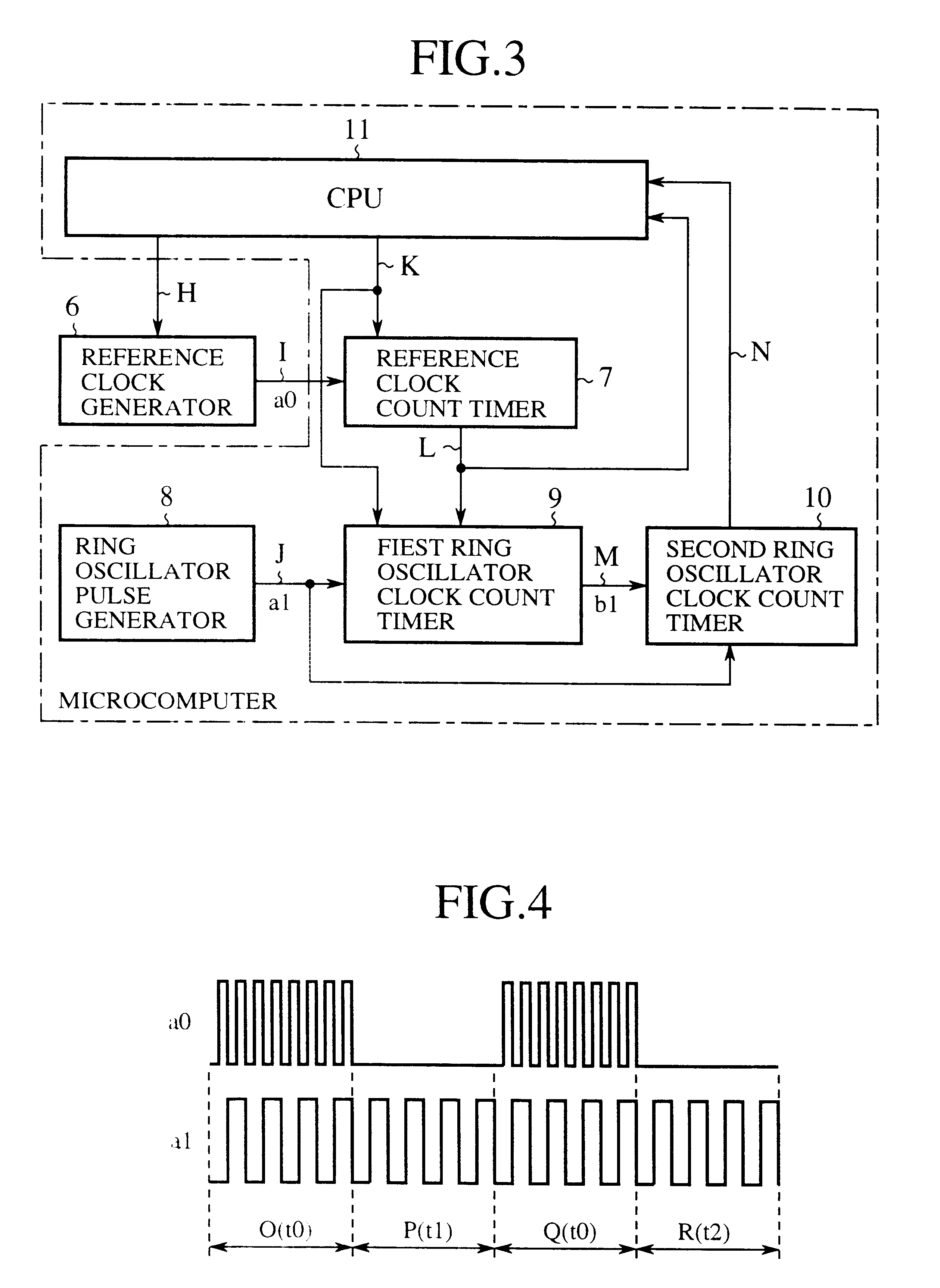
FIG. 3 is a block diagram showing a microprocessor of an embodiment 2 in accordance with the present invention. In FIG. 3, the reference numeral 6 designates a reference clock generator that consists of a ceramic oscillator, or the like externally connected to the microprocessor it outputs a reference clock signal a0 through a signal line I in response to a start instruction supplied from a CPU 11 through a signal line H, and stops generating the reference clock signal a0 in response to a stop instruction. The reference numeral 7 designates a reference clock count timer that starts counting the reference clock signal supplied through the signal line I in response to a start instruction fed from the CPU 11 through a signal line K, and outputs an overflow signal through a signal line L when it counts the reference clock signal up to a preset value. The reference numeral 8 designates a ring oscillator pulse generator for outputting a ring oscillator clock signal a1 through a signal lin...


PUM


Abstract

A ring oscillator clock frequency measuring circuit includes a reference clock count timer and a ring oscillator clock count timer. The reference clock count timer starts its counting of a reference clock signal in response to a start instruction fed from a CPU, and outputs an overflow signal when its counting reaches a preset value. The ring oscillator clock count timer starts its counting of pulses of a ring oscillator clock signal in response to the start instruction fed from the CPU, and continues its counting until the reference clock count timer generates the overflow signal. The frequency of the ring oscillator clock signal is obtained from the count value of the ring oscillator clock count timer. This makes it possible to measure the frequency of the ring oscillator clock signal at high accuracy, and to reduce the current consumption by operating the CPU based on the ring oscillator clock signal after the measurement.

Description

1. Field of the InventionThe present invention relates to a ring oscillator clock frequency measuring method, and a ring oscillator clock frequency measuring circuit for measuring the frequency of a ring oscillator clock signal generated by a ring oscillator (square pulse generator), and to a microprocessor operating based on the ring oscillator clock signal.2. Description of Related ArtA pulse train generated by a ring oscillator has large frequency fluctuations due to external factors such as temperature and process parameter, and hence an external oscillator like a ceramic oscillator is needed by a system requiring high frequency accuracy. Thus, a conventional system requiring high frequency accuracy cannot use a ring oscillator clock signal, but employs an external oscillator with greater current consumption than the ring oscillator.Japanese patent application laid-open No. 58219625 / 1983 discloses techniques about such conventional ring oscillator clock frequency measurement and...

Claims


Application Information

Patent Timeline
IPC IPC(8): G01R23/02G01R23/00H03K5/19G06F1/04G01R23/10G01R23/15H03K3/03
CPCG01R23/02H03K5/19
Inventor MORIMOTO, YASUFUMIFUJII, TAKESHI
Owner MITSUBISHI ELECTRIC SYST LSI DESIGN
Why Eureka
Try Eureka