Metering unit for a fuel injection system for internal combustion engines

Inactive Publication Date: 2002-09-10
ROBERT BOSCH GMBH
View PDF7 Cites 37 Cited by
  • Summary
  • Abstract
  • Description
  • Claims
  • Application Information

AI Technical Summary

Problems solved by technology

This latter fractional stream is the overflow quantity, which at the same time means an attendant loss of efficiency.
This leads to high fuel temperatures and poor efficiency.
Furthermore, the wide fuel temperature range in operation wit

Method used


Image

  • Metering unit for a fuel injection system for internal combustion engines
  • Metering unit for a fuel injection system for internal combustion engines
  • Metering unit for a fuel injection system for internal combustion engines

Examples


Example

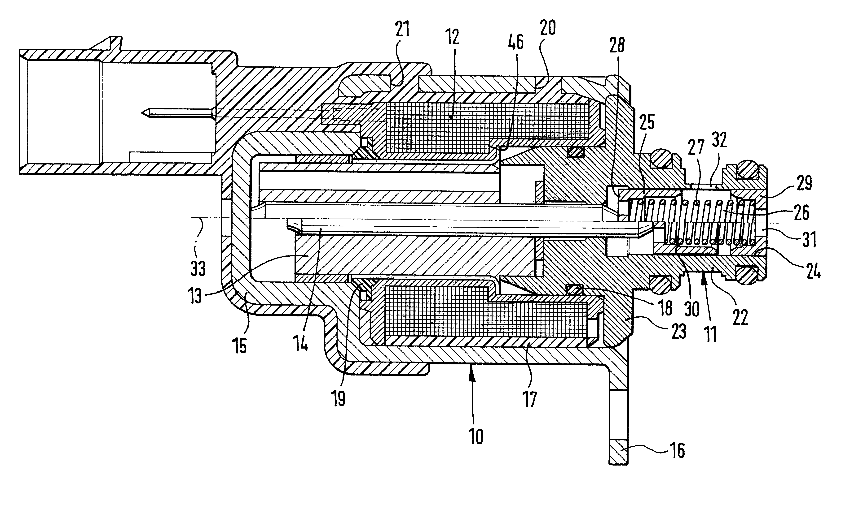
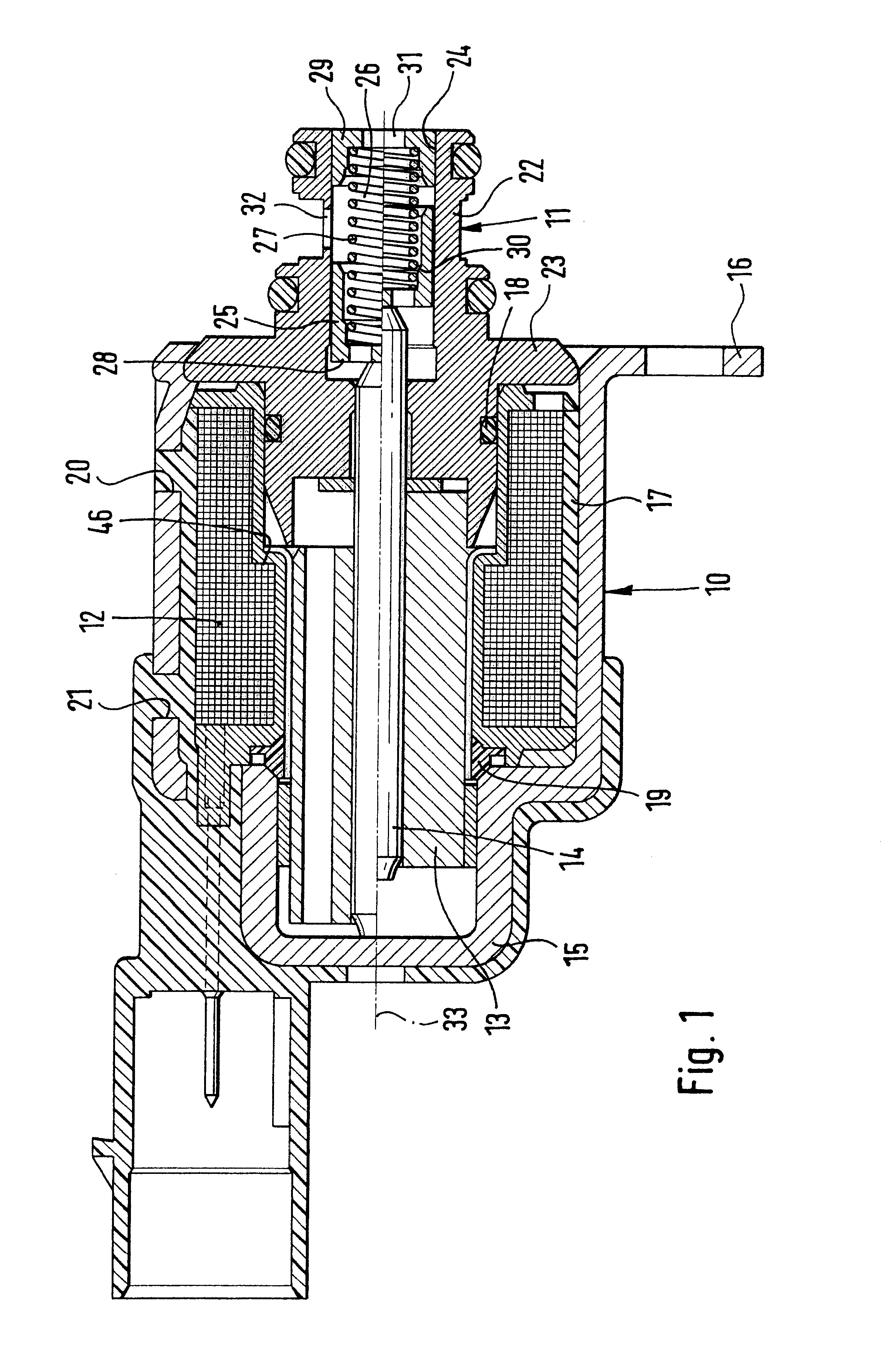
The fuel metering unit of FIG. 1 is based on an electromagnet 10 with an integrated regulating valve 11. Specifically, the electromagnet 10 substantially comprises a magnet, coil 12, an armature 13 with an armature bolt 14, and a magnetic housing 15 that partly surrounds the magnetic oil and the armature 13.

The entire structural unit of the electromagnet 10 with the integrated regulating valve 11 is disposed in a high-pressure fuel pump (not shown). The magnetic housing 15 simultaneously serves as a sealing element and as a magnetic short circuit, and has a fastening element 16 integral with the housing that helps to mount the electromagnet 10 in the high-pressure pump.

The magnet coil 12, once it is inserted into the magnet housing 15, is spray-coated completely. The spray coating 17 assures an optimal heat transfer from the coil 12 to the housing 15. Overheating in critical operating states can be counteracted as a result. The spray coating 17 also leads to good resistance to vibra...


PUM


Abstract

A fuel injection system for internal combustion engines, has a distributor tube and a high-pressure pump that is driven as a function of engine rpm and that serves to generate the fuel pressure and throughput required in the distributor tube in the applicable operating state of the engine. The system also includes a fuel metering unit, which is associated with the high-pressure pump and includes a regulating valve which is actuated electromagnetically. The fuel metering unit is disposed in the high-pressure pump, and the outlet of the regulating valve discharges into the low-pressure region of the high-pressure pump. The above design features make a fuel metering unit possible that is capable of metering the exact quantity of fuel desired in the applicable engine operating state to the high-pressure pump of the CR system.

Description

PRIOR ARTThe invention relates to a fuel injection system for internal combustion engines.As general prior art in this field, European Patent Disclosure EP 0 299 337 and German Patent Disclosure DE 195 49 108.4 are cited--as examples.In particular, the invention is based on a so-called common rail system (CR system). The special feature of such CR systems is that the requisite fuel quantity has to be brought by a high-pressure pump to a variable pressure that is dependent on the applicable engine operating state. The high-pressure pump is driven as a function of the engine rpm, which can be done by cam shaft drive, for instance. The possible feed quantity of the high-pressure pump is designed such that in every operating state, an excess quantity of fuel, that is, more than is needed by the rail for the desired pressure buildup, can be pumped.It is known for the fuel to be metered to the rail on the basis of a pressure regulating valve that is disposed in the high-pressure region do...

Claims


Application Information

Patent Timeline
IPC IPC(8): F02M59/34F02M63/02F02M59/46F02M59/20F02M63/00F02M59/00
CPCF02M59/34F02M63/0017F02M63/004F02M63/0045F02M63/0056F02M63/0225F02M2200/24
Inventor KRIMMER, ERWINHAEBERER, RAINERCLAUSS, HELMUTMIEHLE, TILMANLAUDAEUSSER, FELIXRUECKLE, MARKUS
Owner ROBERT BOSCH GMBH
Why Eureka
Try Eureka