Determining phase of AC mains in PWM controlled converters without voltage sensors

a technology of voltage sensor and ac mains, which is applied in the direction of ac-ac conversion, power conversion system, conversion with intermediate conversion to dc, etc., can solve the problems of increased system cost due to additional required components, reduced reliability, and increased number of components

Inactive Publication Date: 2002-10-01
OTIS ELEVATOR CO
View PDF3 Cites 32 Cited by
  • Summary
  • Abstract
  • Description
  • Claims
  • Application Information

AI Technical Summary

Benefits of technology

FIG. 2 is a functional block diagram of a pulse width modulation-controlled converter of th

Problems solved by technology

There are several disadvantages to this approach for determining the phase angle.
System cost is increased due to the additional required components, particularly due to the isolation amplifiers that are expensive.
Reliability is decreased due to the increased number of compon

Method used


Image

  • Determining phase of AC mains in PWM controlled converters without voltage sensors
  • Determining phase of AC mains in PWM controlled converters without voltage sensors
  • Determining phase of AC mains in PWM controlled converters without voltage sensors

Examples


Embodiment Construction

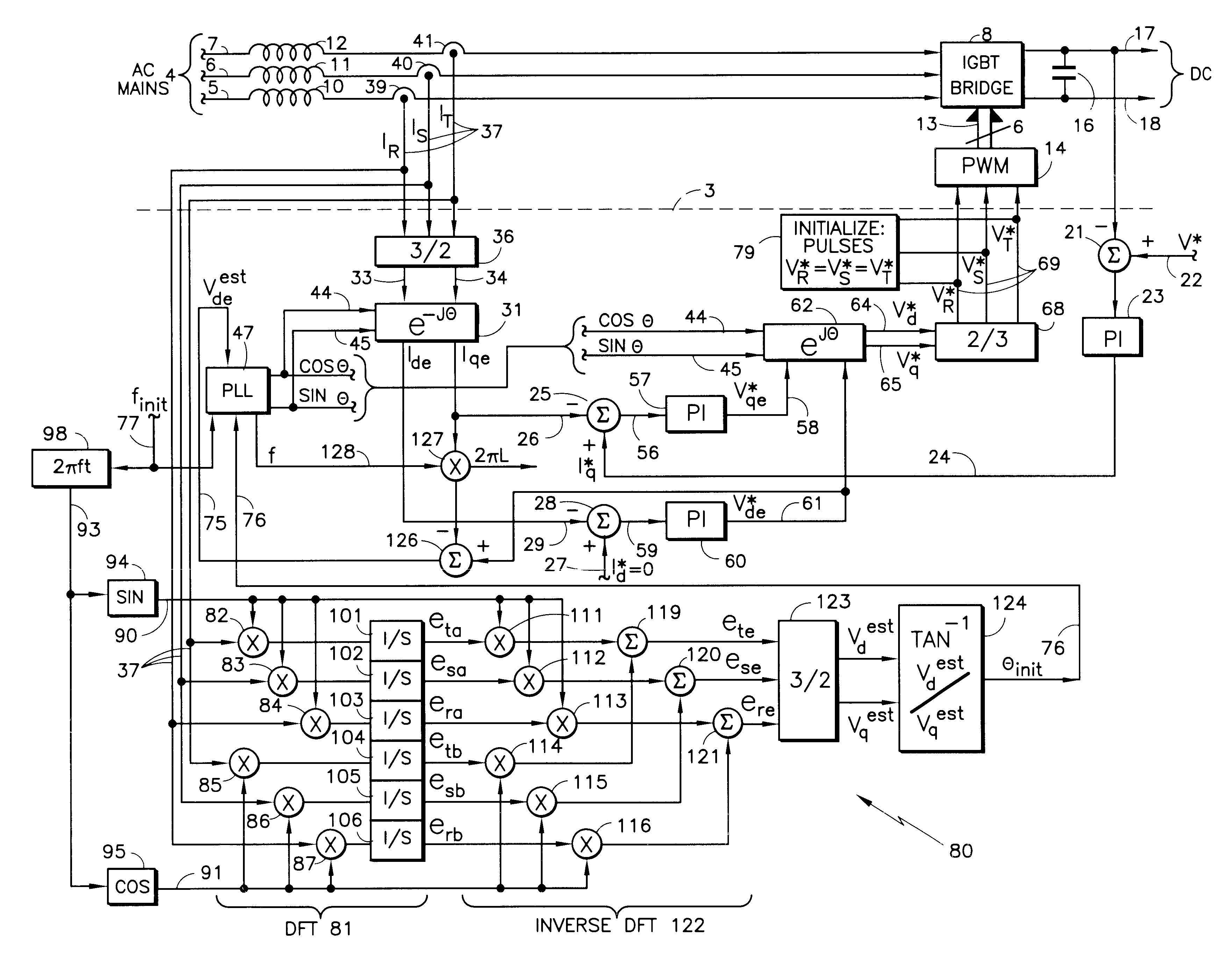
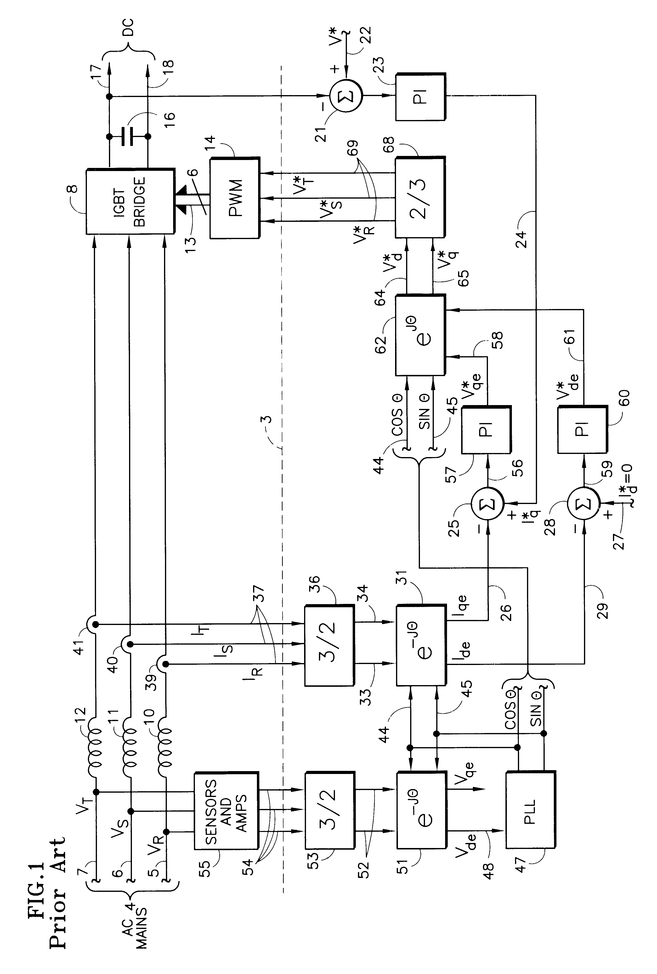
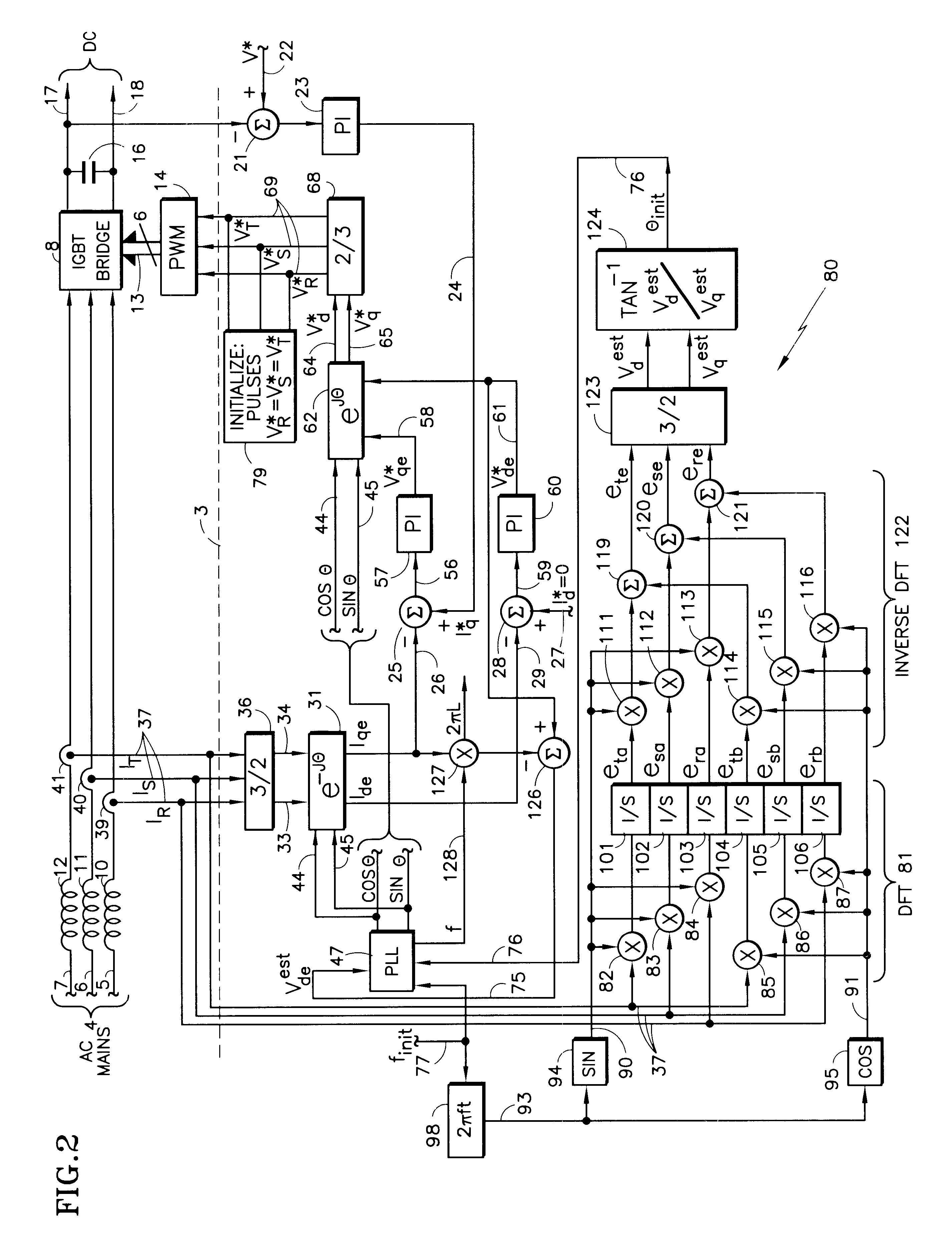
In FIGS. 1 and 2, the functions illustrated above the dotted line 3 are provided by hardware, whereas the functions illustrated below the dotted line 3 are provided by software, as is conventional.

Referring to FIG. 1, the AC mains 4 include R, S and T phases 5-7 as is known. The AC mains 4 are applied through line inductors 10-12 to a conventional insulated gate bipolar transistor bridge 8, which receives six different switching signals over lines 13 from a conventional pulse width modulation controller 14. The bridge 8 provides regulated DC voltage to a power capacitor 16 and a pair of output lines 17, 18.

A signal indicative of the DC voltage of the line 17 is applied to a negative input of a summing function 21, the positive input of which is the desired or commanded voltage V* on a line 22. In an elevator system, this command is provided by the motion controller; in other systems, other commands may be used. The difference is applied to a proportional and integral controller 23 w...


PUM


Abstract

In a pulse width modulation-controlled, switched bridge, DC converter, the phase angle (44, 45) of the AC mains (4) is provided without sensing the voltage thereof, by a phase-locked loop (47) having one input (75) derived (126) from the in-phase voltage command Vde* (61) and another finit (77) approximating the line frequency; the phase-locked loop is initialized at a phase angle thetainit(76) equal to the arctangent (124) of the in-phase Vdest, and quadrature Vqest representation of estimated line voltages ere, ese, ete (119-121) derived during an initialization cycle from reconstruction of the fundamental component of the AC main currents at a phase angle (93) changing with said frequency. Reconstruction includes providing the discrete Fourier transform (DFT, 81) of signals indicative of currents (37) in the AC mains and the inverse DFT (122) of the resultant Fourier coefficients eia, eib.

Description

This invention relates to provision of the phase angle of voltage on AC mains for use in a conventional pulse width modulation-controlled voltage source converter employing an insulated gate bipolar transistor (IGBT) bridge, without measuring the voltage of the mains, utilizing signals indicative of the currents in the mains.Regenerative drives in elevators are attractive since they can transfer energy stored in an overrunning elevator (the elevator load driving the motor) back to the building power supply, resulting in increased energy efficiency and reduced operating costs for the building owner. Proper operation of a regenerative drive requires knowledge of the phase angle of the AC power supply in order to control the energy flow to / from the power supply. Historically, the phase angle has been determined by measuring each of the three power supply phase voltages using a sensing circuit that is typically comprised of high-voltage resistors and isolation amplifiers. The resulting ...

Claims


Application Information

Patent Timeline
IPC IPC(8): H02M7/219
CPCH02M7/219
Inventor AGIRMAN, ISMAILBLASKO, VLADIMIRCZERWINSKI, CHRISTOPHER S.IZARD, JEFFREY M.PIEDRA, EDWARD D.
Owner OTIS ELEVATOR CO
Why Eureka
Try Eureka