Signal processing method and apparatus for computing an optimal weight vector of an adaptive antenna array system

a signal processing and weight vector technology, applied in diversity/multi-antenna systems, direction finders using radio waves, instruments, etc., can solve the problems of inability to cope with the rapid growth of demand for current techniques, inability to achieve real-time complexity without loss of accuracy, and many serious difficulties in applying the theory of [1] to the actual wireless communication world

Inactive Publication Date: 2002-10-08
INTELLECTUAL DISCOVERY CO LTD
View PDF11 Cites 46 Cited by
  • Summary
  • Abstract
  • Description
  • Claims
  • Application Information

AI Technical Summary

Problems solved by technology

However, since the autocovariance matrices R.sub.y and R.sub.u should be computed from the expectation of the power of y and u, it is never possible in actual signal environment to form the equation (1) at every snapshot for each of which the optimal weight vector should be computed.
Even if the equation is formed somehow, since the computation of an eigenvector corresponding to the largest eigenvalue of a generalized eigen-problem requires a lot of computations, there arises many serious difficulties in applying the theory of [1] to the actual wireless communication world.
However, due to the limit of conventional techniques as mentioned above, it seems impossible to cope with the rapidly growing demand with the current techniques.
Therefore, it is extremely and desperately required to develop a new technology for designing a smart antenna system enhancing the communication capacity and communication quality with a realizable complexity without loss of accuracy because of the simplicity.

Method used


Image

  • Signal processing method and apparatus for computing an optimal weight vector of an adaptive antenna array system
  • Signal processing method and apparatus for computing an optimal weight vector of an adaptive antenna array system
  • Signal processing method and apparatus for computing an optimal weight vector of an adaptive antenna array system

Examples


first preferable embodiment

As the first preferable embodiment, this invention discloses a method of computing the weight vector with an eigenvector corresponding to the largest eigenvalue of the eigen-problem (3) by updating the weight vector through the procedure of (7) at each snapshot such that (5) can be maximized, which is an application of the prior art, Lagrange's formula. The adaptive procedure based on the Lagrange's formula can be applied to mobile communications through the three steps as follows:

Set up an initial guess for the weight vector w. For an efficient convergence, it is recommended have the normalized and received signal vector after the despreading procedure as the initial value, i.e., y(0) / .parallel.y(0).parallel. where .parallel.y(0).parallel.=(y.sup.H (0)y(0)).

Update the autocovariance matrices, R.sub.x (pre-correlation autocovariance matrix) and R.sub.y (post-correlation autocovariance matrix), with the received signal vector x(n) (a pre-correlation signal vector) and y(n) (post-co...

second preferable embodiment

In this preferable embodiment, an adaptive procedure of computing an eigenvector corresponding to the smallest eigenvalue of (4). The technique ultimately searches for the same weight vector that converges to an eigenvector corresponding to the largest eigenvalue of (3). To find the target eigenvector corresponding to the smallest eigenvalue of (4), the signal index x representing pre-correlation and y representing post-correlation are interchanged in and the sign of (11) is changed as follows:

w.rarw.w-.mu.[R.sub.x w-.lambda.R.sub.y w] (12)

The adaptive procedure of finding an eigenvector corresponding to the smallest eigenvalue of (4), instead of that corresponding to the largest eigenvalue of (3), can be summarized as follows:

Set up an initial guess w.

Update the autocovariance matrices, R.sub.x denoting a pre-correlation autocovariance matrix and R.sub.y denoting a post-correlation autocovariance matrix, with the received signal vector x(n) denoting a pre-correlation signal vect...

third preferable embodiment

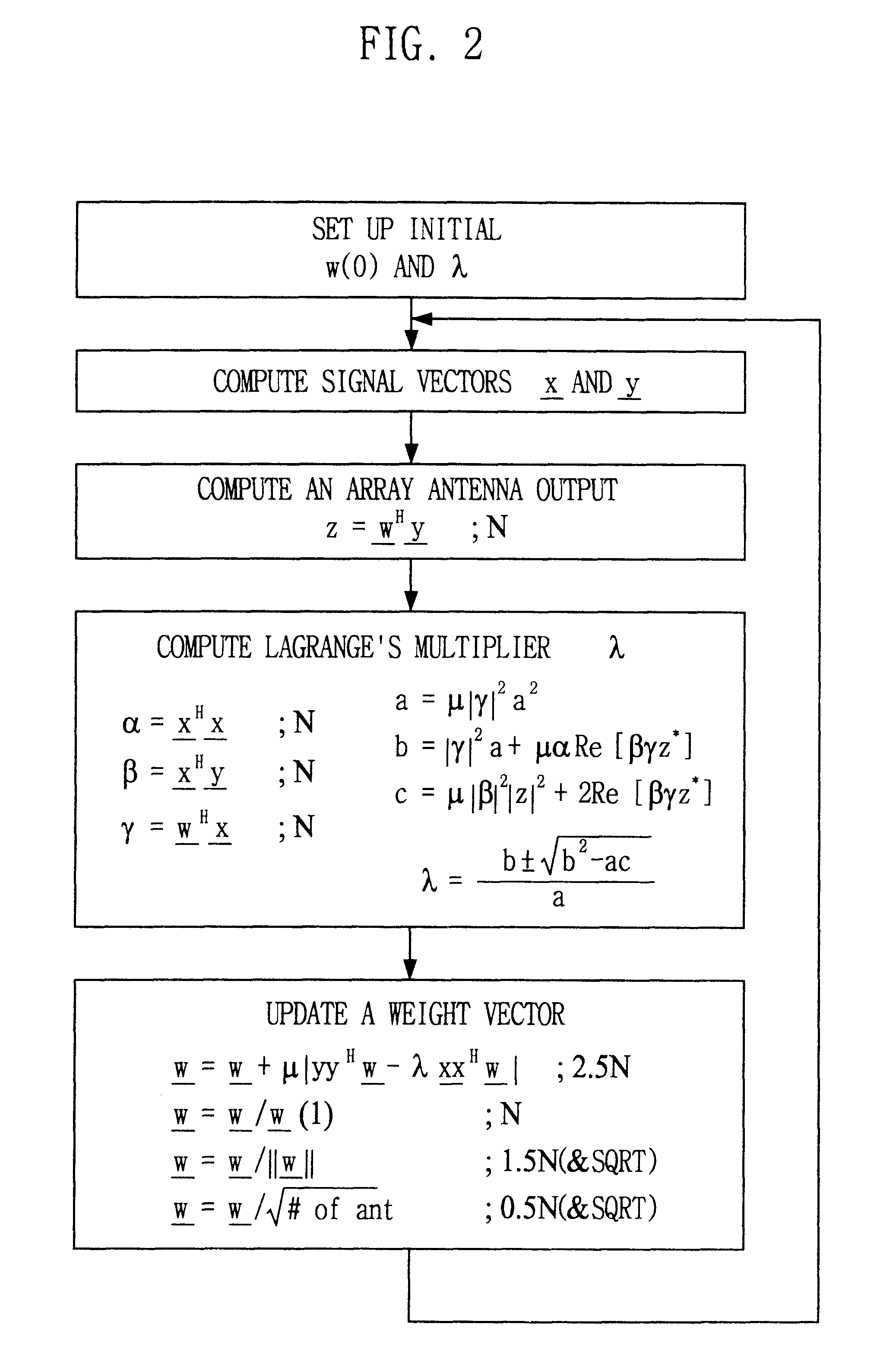
The simplified adaptive procedure of computing the weight vector with an eigenvector corresponding to the largest eigenvalue of (3), excluding all the matrix operations, can be summarized as follows:

Set up an initial guess of the weight vector w. As in the other preferable embodiments, for a fast convergence, the received signal vector obtained at the output of the despreader, i.e., y(0) / .parallel.y(0).parallel., is recommended for the initial guess where .parallel.y(0).parallel.=(y.sup.H (0)y(0)).

Compute the Lagrange multiplier .lambda. at the present snapshot from the present weight vector w, the received signal vectors x representing pre-correlation RX signal vector and y representing post-correlation RX signal vector, and a preset adaptive gain .mu. as follows: ##EQU10##

where a=.mu..vertline..delta..vertline..sup.2.alpha..sup.2, b=.vertline..delta..vertline..sup.2.alpha.+.mu..alpha.Re[.gamma..delta.z*] and c=.mu..vertline..gamma..vertline..sup.2.vertline.z.vertline..sup.2 Re[....


PUM


Abstract

This invention relates to a signal processing method and apparatus for an adaptive array antenna. The objective is to suggest an adaptive procedure of computing the suboptimal weight vector for an array antenna system that provides a beampattern having its maximum gain along the direction of the mobile target signal source in a blind signal environment, where the transmitted data are not known (or not to be estimated) at the receiver. It is the ultimate goal of this invention to suggest a practical way of enhancing both the communication quality and communication capacity through the optimal weight vector of the array system that maximizes SINR(Signal to Interference+Noise Ratio). In order to achieve this goal, the method of Lagrange multiplier is modified in such a way that the suboptimal weight vector is produced with the computational load of about O(8N), which has been found to be small enough for the real-time processing of signals in most land mobile communications with the digital signal processor (DSP) off the shelf, where N denotes the number of antenna elements of the array.

Description

The present invention relates to a technique utilizing an array antenna; and, more particularly, to a method and apparatus for optimizing the beam pattern of an array antenna system and its applications to transmitting and receiving systems by finding a weight vector capable of maximizing the signal to interference plus noise ratio in as accurate and simple way as possible.An antenna system that improves the performance of a wireless communication with a proper beam pattern is generally referred to as "smart antenna system (SAS)". A theory related to the design of the SAS from a weight vector that maximizes the signal to interference plus noise ratio has been published in a prior art, [1]Ayman F. Naguib, "Adaptive Antennas for CDMA Wireless Networks", Ph. D. Dissertation, Dept of Electrical Engineering, Stanford University, August 1996. In [1], the weight vector is obtained from an eigenvector corresponding to the largest eigenvalue of a generalized eigen-problem as follows:R.sub.y ...

Claims


Application Information

Patent Timeline
Patent Type & Authority Patents(United States)
IPC IPC(8): H01Q3/26H04B7/08H01Q23/00H01Q21/00
CPCH01Q3/2605H04B7/0854H01Q21/00H01Q23/00
Inventor CHOI, SEUNG-WON
Owner INTELLECTUAL DISCOVERY CO LTD
Why Eureka
Try Eureka