
Self-aligning splined male shaft head and engagement method

a splined male shaft head and self-aligning technology, which is applied in the direction of screw, interlocking clutch, coupling, etc., can solve the problems of not being able to insert the shaft head into the hub, not being able to wear the front edges of the spline teeth, and being difficult and problematic to achieve the connection

Inactive Publication Date: 2002-11-19
SCHENCK ROTEC GMBH
View PDF8 Cites 150 Cited by
  • Summary
  • Abstract
  • Description
  • Claims
  • Application Information

AI Technical Summary

Benefits of technology

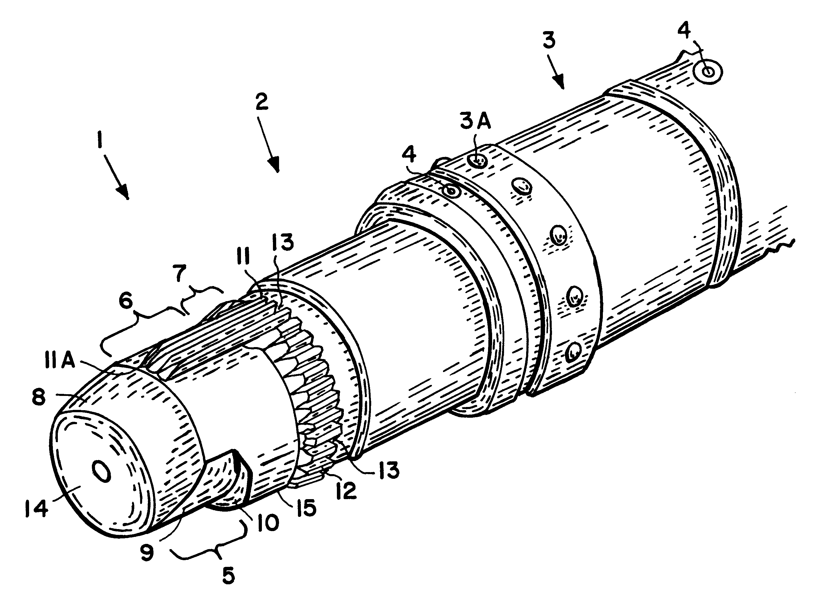
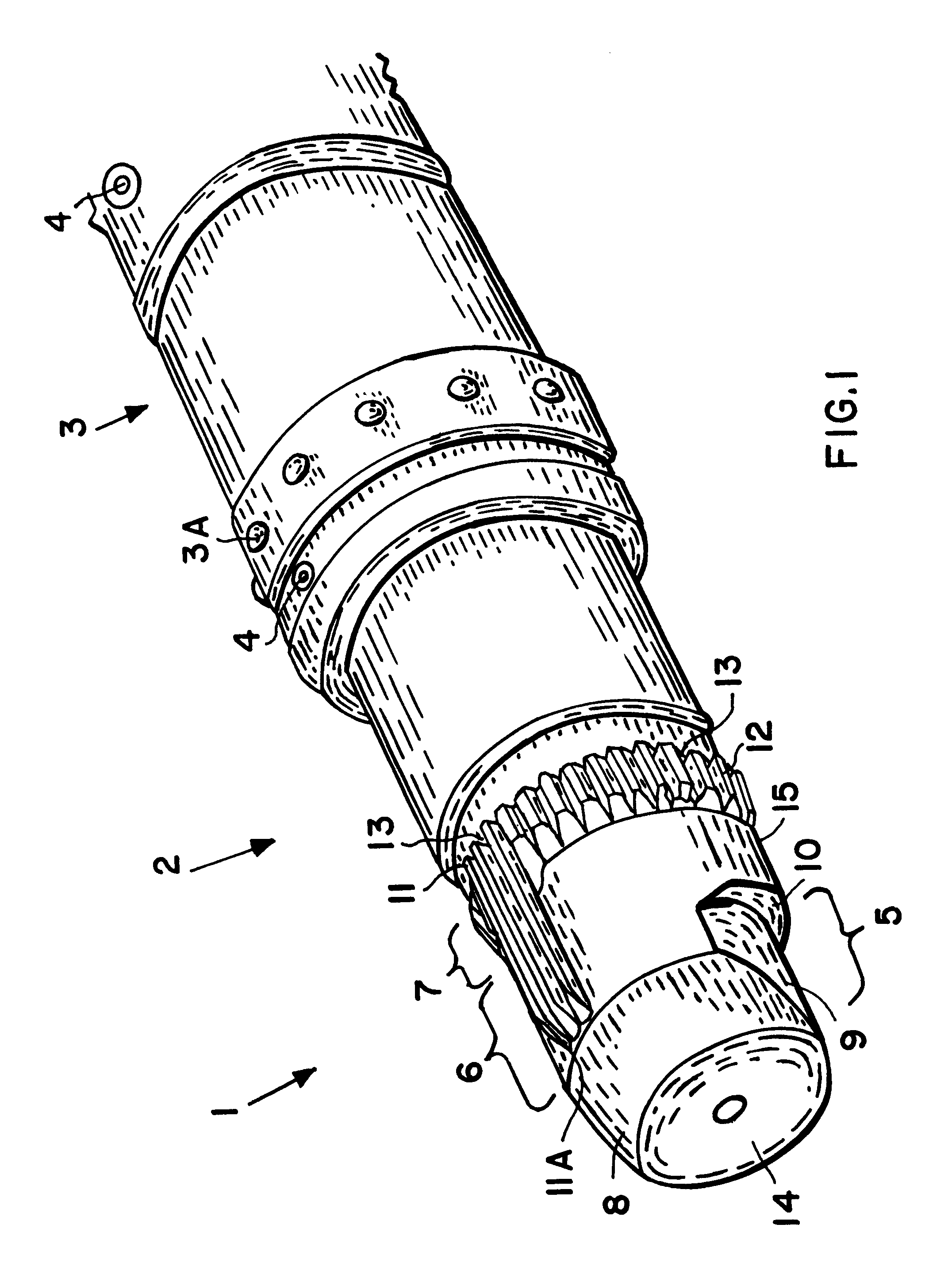
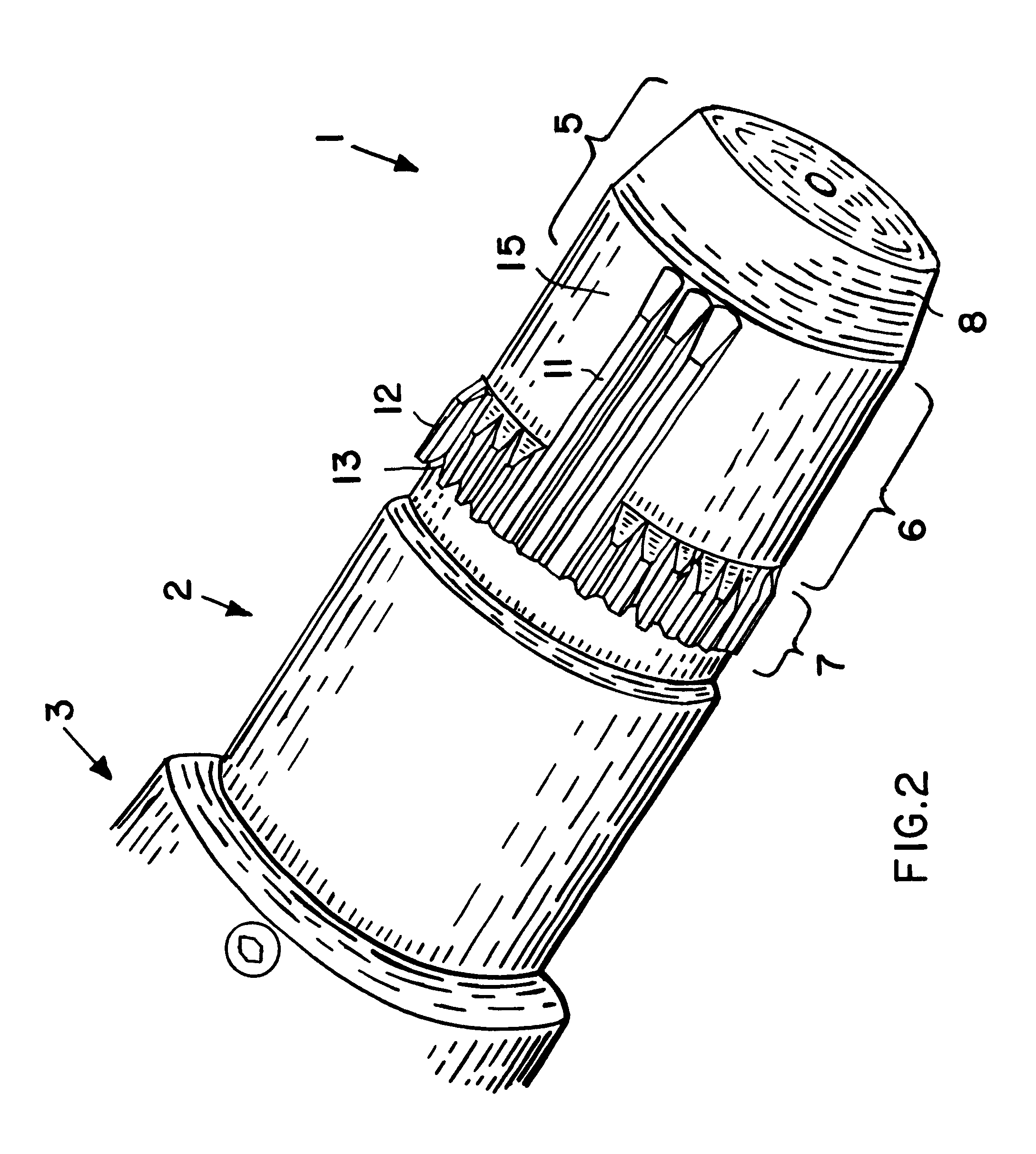
The above objects have been achieved according to the invention in a splined shaft head having a special configuration including distinct first, second and third stages, and in a special insertion method. The first stage, which adjoins and extends rearwardly from a forward free end of the shaft head, includes an outer contour that is not rotationally symmetrical and is eccentrically offset in a first radial direction relative to a major central shaft axis of the shaft head, about which the shaft head is rotatable. This first stage allows the shaft head to be inserted into the hub without requiring perfect co-axial alignment thereof. The second stage of the shaft head adjoining the first stage includes at least one lead spline tooth that is arranged on a side of the shaft head located in the first radial direction relative to the major central shaft axis and that rotationally aligns and pre-engages the shaft head into the hub. Next, the third stage includes at least one main spline tooth that fully engages the shaft head into the hub in a torque-transmitting manner.
The insertion of the shaft head into the hub is preferably carried out by simultaneously rotating and axially advancing the shaft head relative to the hub, without requiring a precise alignment thereof. Instead, it is only necessary to coarsely align the shaft head with the hub, so that the reduced outer dimension of the first stage of the shaft head will go into the open mouth of the hub. As the forward end of the shaft head is introduced into the hub, the eccentrically offset outer contour of the first stage serves to provide a radial play between the shaft head and the hub, whereby the range of this radial play is radially eccentrically offset or un-centered in the first radial direction relative to the central longitudinal shaft axis of the shaft head. Thereby the shaft head promotes a preferential de-centering of the hub relative to the shaft axis of the shaft head in the first radial direction radially outwardly toward the lead spline teeth, i.e. so as to provide radial free play on the side of the lead spline teeth. At a minimum, the shape of the first stage, as it is inserted into the hub, prevents the hub from being de-centered in a radial direction opposite the lead spline teeth, and instead pulls the hub radially toward the lead spline teeth at least into a centered position. This ensures that the shaft head can be inserted into the hub, even if there is initially not a perfect coaxial alignment between the shaft axis of the shaft head and the rotational axis of the hub. This also ensures that the lead spline tooth or teeth of the second stage will accurately engage the splined grooves of the hub.
Namely, as the second stage is inserted into the hub, the at least one lead spline tooth will rotate and axially advance (with the rotating and axially advancing shaft head) relative to the non-rotating hub, until this at least one lead spline tooth comes into rotational alignment with a corresponding spline groove of the hub and axially advances into engagement with this spline groove to establish a pre-engagement of the shaft head with the hub, whereby the hub is then carried along to rotate with the shaft head. Preferably, the first stage overlaps with the second stage, so that the at least one lead spline tooth engages into a respective spline groove of the hub while the hub is still de-centered or provided with a de-centered radial play relative to the shaft axis of the shaft head. This de-centering and the smaller outer dimension of the first stage allows a sufficient degree of play between the shaft head and the hub during insertion of the first stage (and beginning of the second stage) into the hub, to allow the one or more lead spline teeth of the second stage to engage into corresponding spline grooves of the hub, even if the shaft head and the hub were initially not in rotational and radial, i.e. coaxial, alignment with each other. This effect is especially achieved by rotating the shaft head while axially inserting it into the hub. Thereby, the shaft head "finds" its proper rotational alignment with the hub during the insertion of the first stage and then the second stage into the hub.
The present inventive shaft head and method for its use provide a simpler shaft head structure, and a simpler process for engaging the shaft head into a hub, in comparison to the prior art. Also, tests that have been carried out using a shaft head according to the invention have shown that the inventive shaft head suffers reduced wear, avoids jamming due to mis-alignment in a splined hub, and achieves improved precision and reproducibility of a play-free form-locking engagement of the shaft head with a hub. A surprisingly high degree of precision without play, essentially a completely rigid, as-if-integral, connection between the hub and the shaft head is reproducibly achieved.

Problems solved by technology

While the above described typical splined interconnection between the shaft head and the hub provides a good positive form-locking connection for torque transmission between the two components, it is generally difficult and problematic to achieve the connection Namely, in order to insert the splined male shaft head into the splined hub, the shaft head and the hub must be precisely aligned with each other in terms of their respective radial positions and in terms of their respective rotational positions.
Otherwise, it will not be possible to insert the shaft head into the hub, due to the blocking contact of the spline teeth of the two components with each other.
Moreover, if there is only a slight misalignment between the two parts, in either the rotational or radial directions, the front edges of the spline teeth will suffer wear, which becomes cumulative over the course of repeatedly connecting and disconnecting the shaft head to and from mating splined hubs.
The above described spring-loaded shaft head, however, suffers several disadvantages and problems in actual use.
Also, the moveable spring-loaded arrangement of these teeth sometimes leads to jamming of the shaft head with an improper alignment relative to the hub.
As a result of the loose or yielding arrangement, and especially further in view of the resulting wear and occasional jamming, the spring-loaded shaft head cannot ensure a high degree of precision and play-free engagement between the shaft head and the hub.
As a further disadvantage, such a spring-loaded shaft head suffers high costs and effort with regard to the initial manufacturing and installation thereof, and in relation to ongoing maintenance and replacement thereof, especially in view of the assembly of separate moving parts that is required.
A particular example is the unbalance measuring and balancing of torque converters used in the drive trains of motor vehicles and the like.
The above application of torque converter balancing places high demands on the splined shaft head of the second tooling that engages the inner parts of the torque converter.
This leads to rapid cumulative wear of the splined shaft head as generally discussed above.
Also, since the unbalance measuring operation requires extreme precision and a play-free rotational interconnection between the tooling shaft head and the torque converter turbine hub, the splined shaft head must ensure such a precise play-free engagement in the hub.
Furthermore, this precision and play-free engagement must be consistent or reproducible between the first unbalance measuring run and the audit run, or otherwise any play or the like would have an effect on the unbalance measurement and result in erroneous data giving the appearance that the balancing procedures were not effective.
This would lead to a continuously repeated sequence of measuring and balancing steps without ever achieving a certifiable proper balance.
When the above described conventional splined shaft heads have been used to provide the required connection to the torque converter turbine hub in this context, they have not been able to achieve high-accuracy satisfactory results.
To the contrary, the conventional splined shaft heads suffer rapid wear and a somewhat loose connection with play leading to imprecise unbalance measuring results.
Also, it has been a continuing difficulty to achieve the required rotational and radial alignment of the shaft head relative to the torque converter turbine hub for engaging the shaft head into the hub.
Difficulties encountered while coupling the torque converter to the balance measuring equipment lead to extra effort and time, which in turn lead to extra costs in the overall manufacturing of the torque converters.

Method used


Image

  • Self-aligning splined male shaft head and engagement method
  • Self-aligning splined male shaft head and engagement method
  • Self-aligning splined male shaft head and engagement method

Examples


Embodiment Construction

FIG. 1 shows a general schematic perspective view of a shaft head 1 according to the invention mounted or held in a shaft head holder or chuck 2 which in turn is mounted in or on a tool shaft 3. The shaft head 1 and the shaft head holder 2 may be a single integral piece, but are preferably separate pieces as in the present example embodiment, to allow a cost effective exchange of only the shaft head 1 in the event that it becomes worn or damaged over long term use, or to allow differently dimensioned splined hubs to be accommodated by simply changing the shaft head 1. The connections of the respective parts can be achieved by a form-locking plug-in shape of each part into the next part, and / or by securing with set screws 4 or the like.

The tool shaft 3 can be any rotating shaft that is to be releasably or temporarily connected to a rotatable hub. In the present example embodiment, the tool shaft 3 is the rotatable tool shaft of the inner tooling or upper tooling of a torque converter...


PUM


Abstract

A splined shaft head for engaging a splined hub includes first, second and third stages. The first stage has a conical taper on one side, and a cylindrical setback on the other side, which transitions through a tapered shoulder to the cylindrical body of the shaft head. The second stage includes lead spline teeth extending along the cylindrical body to the conical taper. The third stage includes torque-transmitting main spline teeth regularly arranged around the circumference. The shaft head is rotated while being inserted axially into the hub. The first stage allows radial free play and de-centering of the hub so the lead spline teeth find a proper rotational alignment with spline grooves of the hub. Then, the tapered shoulder at the end of the first stage positively centers the hub on the shaft axis, and finally the main spline teeth of the third stage provide full form-locking engagement.

Description

The present invention relates to a male shaft head having spline teeth for engagement into a splined female hub or the like.BACKGROUND INFORMATIONIn many mechanical applications in various different technical fields, it is necessary to temporarily or releasably engage two rotatable members with each other. Predominantly this involves engaging a rotatable male shaft head into a rotatable female hub or other receiver opening. Throughout this specification, the term "hub" will be used generally to refer to any opening or recess adapted to receive a male shaft head therein. The engagement of the male shaft head into the female hub is commonly achieved by providing one or more axially longitudinally extending keys or spline teeth on the outer circumference of the shaft head, and corresponding spline grooves or keyways on the inner circumference of the hub. The splined shaft head further has corresponding spline grooves respectively between neighboring spline teeth, and the splined hub ha...

Claims


Application Information

Patent Timeline
Patent Type & Authority Patents(United States)
IPC IPC(8): F16D11/14F16D1/06F16D11/00
CPCF16D1/06F16D11/14Y10T403/7032F16D2011/008Y10S464/901F16D2001/103
Inventor KEFES, BURKHARD
Owner SCHENCK ROTEC GMBH
Learn More