Optical amplifier with loop mirror filter noise reducer, and loop mirror filter per se

a technology of optical amplifiers and filters, applied in optical amplifiers, lasers, transmission, etc., can solve problems such as reducing the signal-to-noise ratio, affecting the overall signal-to-noise ratio, and not being practical or useful in a real system

Inactive Publication Date: 2002-12-03
OPREL TECH
View PDF9 Cites 1 Cited by
  • Summary
  • Abstract
  • Description
  • Claims
  • Application Information

AI Technical Summary

Problems solved by technology

Unfortunately, spontaneous emission occurs, is amplified along with the input signal, and appears as noise in the output signal, reducing the signal-to-noise ratio.
A disadvantage of Wong et al.
While this might be acceptable in an experimental set-up, it is not practical or useful in a real system.
A disadvantage of this arrangement is that, although gain might be increased, overall signal-to-noise ratio will deteriorate because the signal will pass through the amplifier twice, incurring spontaneous emission noise penalties each time.

Method used


Image

  • Optical amplifier with loop mirror filter noise reducer, and loop mirror filter per se
  • Optical amplifier with loop mirror filter noise reducer, and loop mirror filter per se
  • Optical amplifier with loop mirror filter noise reducer, and loop mirror filter per se

Examples


Embodiment Construction

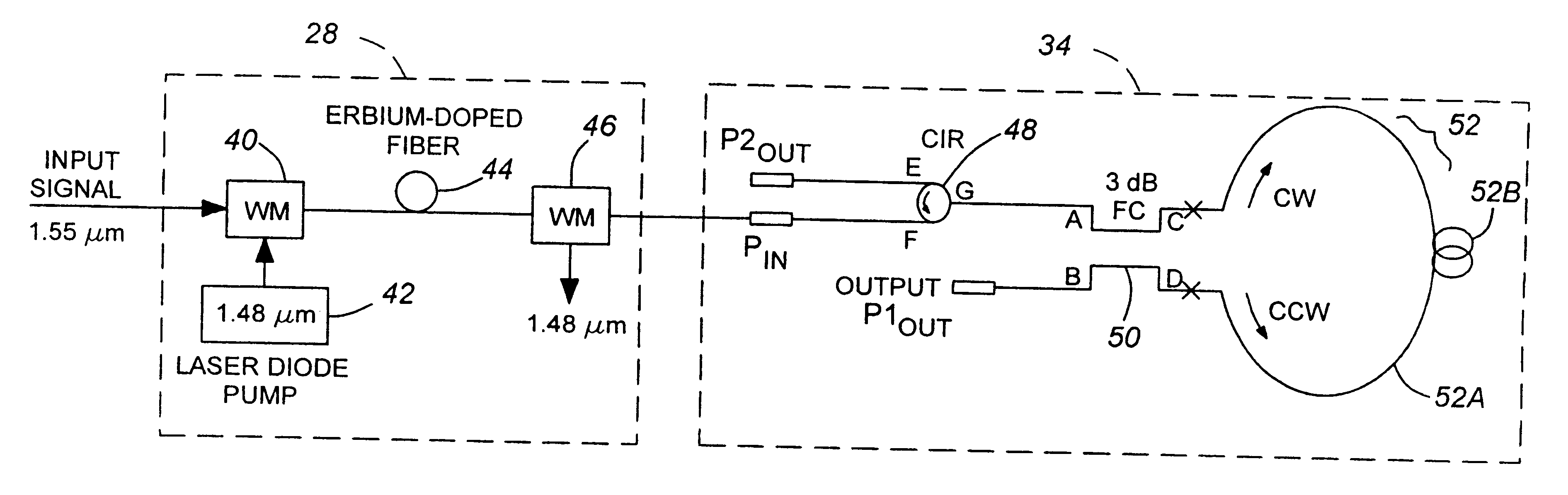
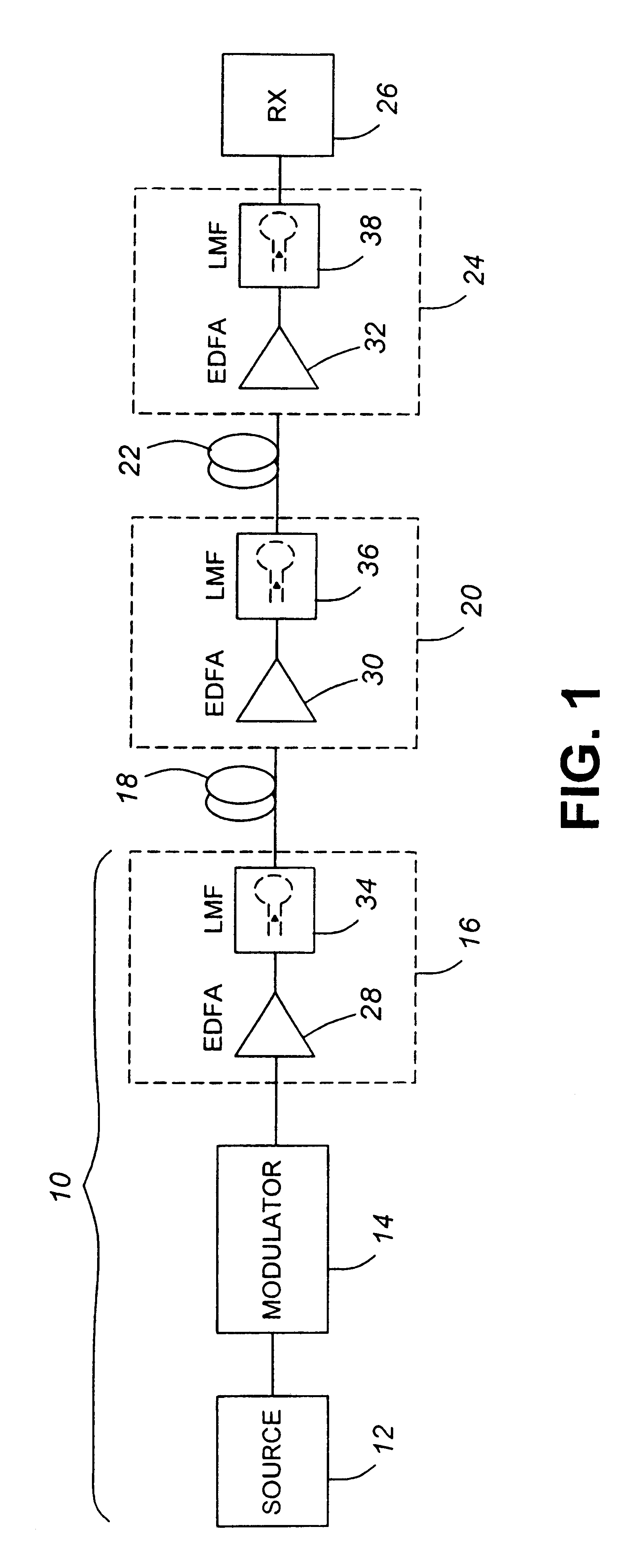
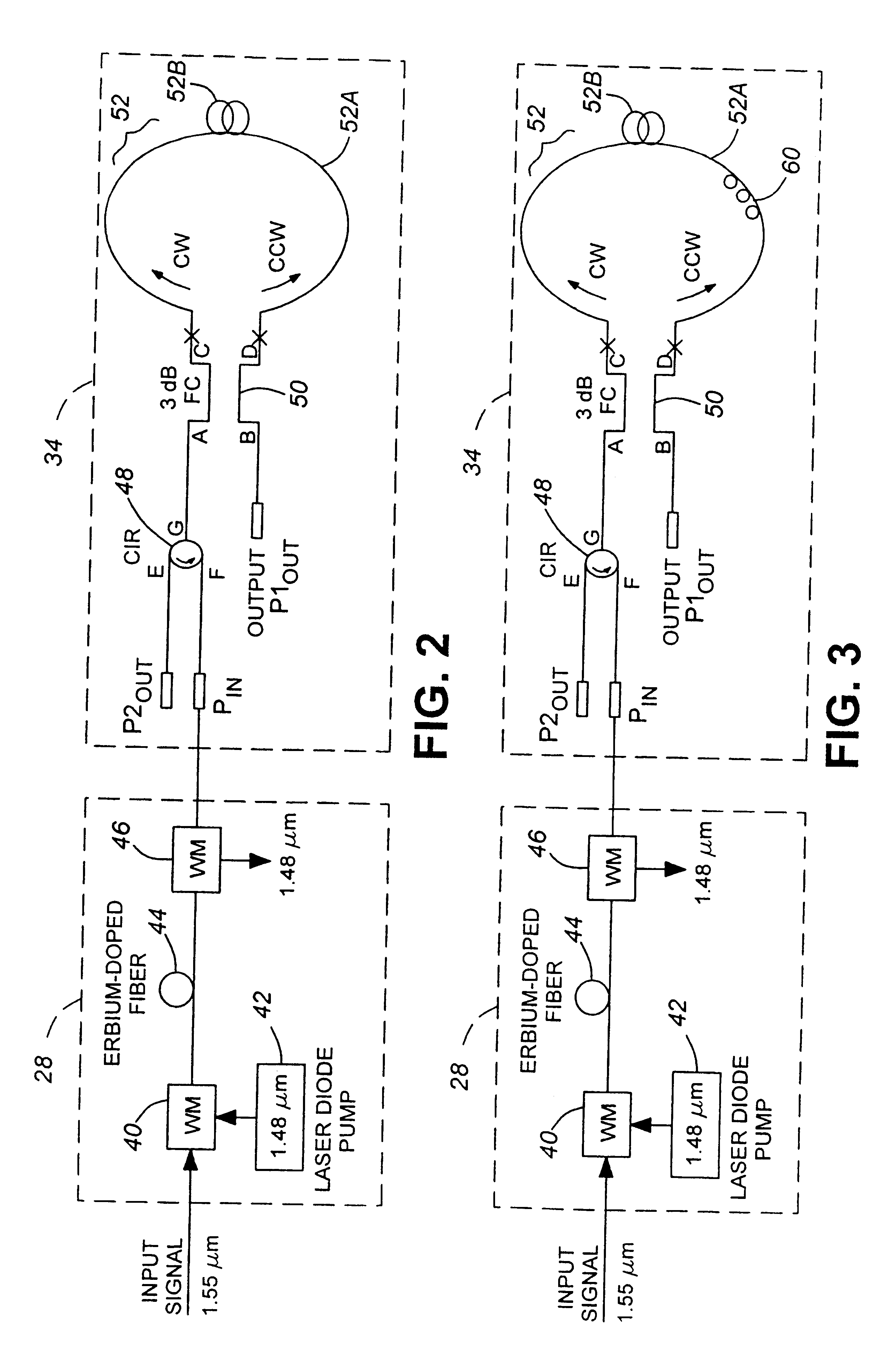
Referring to FIG. 1, an optical telecommunications system comprises a transmitter section 10 comprising a light source 12, conveniently a laser source producing continuous wave (CW) light, a modulator 14, conveniently a lithium niobate device, and an optical power amplifier 16. The modulator 14 is connected between the light source 12 and the input of power amplifier 16 and modulates the CW light with the data to be transmitted. The output of the power amplifier 16 is connected by an optical fiber transmission line 18 to an in-line (repeater) amplifier 20, which is connected in turn by a second optical fiber transmission line 22 to a preamplifier 24, the output of which is connected to a receiver section 26 for extraction of the data in a known manner.

The power amplifier 16, in-line amplifier 20 and preamplifier 24 comprise erbium-doped fiber amplifier stages (EDFAs) 28, 30 and 32, respectively, and loop mirror filters (LMFs) 34, 36 and 38, respectively. The LMFs 34, 36 and 38 remov...


PUM


Abstract

In order to reduce amplified spontaneous emission noise in the output signal of an amplifier of the kind in which amplification introduces amplified spontaneous emission, for example an erbium-doped fiber amplifier, the amplified signal is filtered using a loop mirror filter. The loop mirror filter may comprise a 3-dB fiber coupler with a loop of linear active fiber connected between two of its ports. The amplified signal and the filtered signal may be applied to, and extracted from, one of its other ports, conveniently by way of a circulator.

Description

This invention relates to a loop mirror filter that can be used in optical amplifiers of the kind which employ spontaneous emission, such as, for example, erbium-doped fiber amplifiers.Optical amplifiers are used in optical telecommunications systems at the transmitter, receiver, and as repeaters or in-line amplifiers. Such optical amplifiers typically use an optical fiber doped with a rare earth element, for example erbium, to provide stimulated emission which is used to amplify the signal. Unfortunately, spontaneous emission occurs, is amplified along with the input signal, and appears as noise in the output signal, reducing the signal-to-noise ratio. It is desirable to improve signal-to-noise ratio by removing or substantially reducing such amplified spontaneous emission (ASE) noise.In an article entitled "In-band Amplified Spontaneous Emission Noise Filtering with a Dispersion-imbalanced Nonlinear Loop Mirror", OFC 1999, William S. Wong et at. disclosed an experimental set up wh...

Claims


Application Information

Patent Timeline
Patent Type & Authority Patents(United States)
IPC IPC(8): H01S3/06H01S3/067H01S3/094
CPCH01S3/06754H01S3/06791H01S3/094023H01S2301/02
Inventor ATIEH, AHMAD
Owner OPREL TECH
Why Eureka
Try Eureka