

Phase lock detection circuit for phase-locked loop circuit
- Summary
- Abstract
- Description
- Claims
- Application Information
AI Technical Summary
Benefits of technology
Problems solved by technology
Method used
Image

Examples
Embodiment Construction
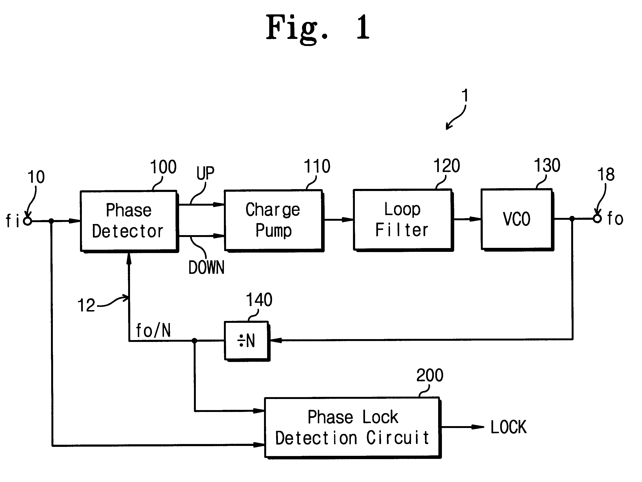
A phase-locked loop circuit 1 with a phase lock detection circuit 200 in accordance with the present invention is shown in FIG. 1. A reference input fi at a terminal 10 provides a stable source of signal. For example, a crystal controlled oscillator(not shown) can be coupled to the terminal 10. A phase detector 100 compares the reference input fi with a divided output signal of / N in order to produce an up control signal and a down control signal. The up and down control signals are supplied to a charge pump 110 to source current or sink current. A loop filter 120 supplies a control voltage to a voltage controlled oscillator (VCO) 130. Thus, an output signal of at a terminal 18 represents an output of the VCO 130. A frequency divider 140 is programmed to produce a division ratio of N.
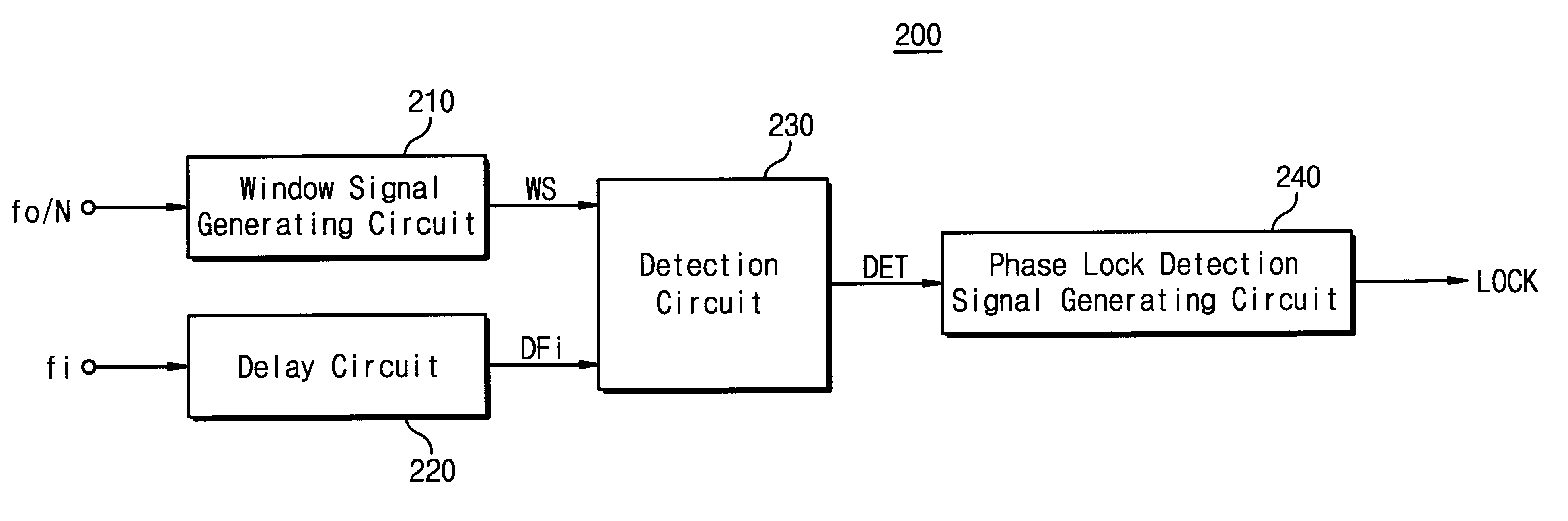
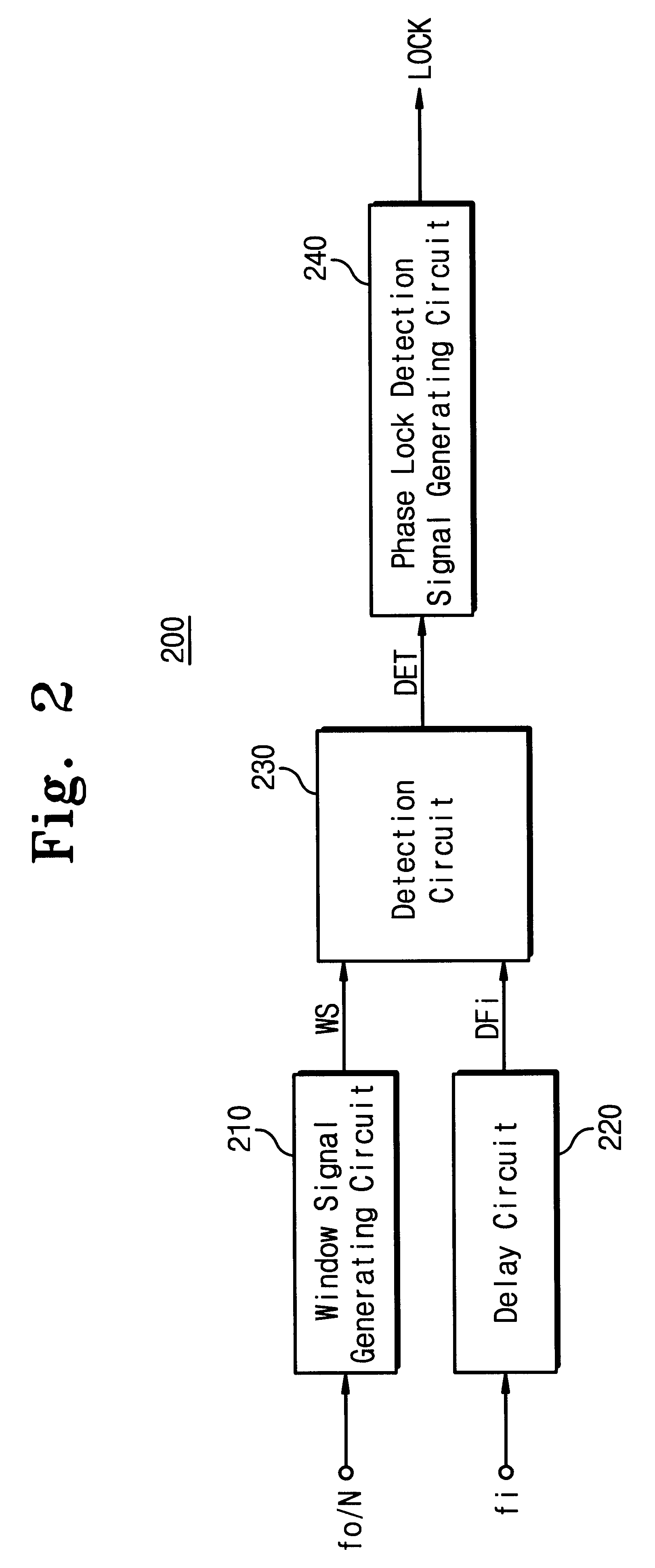
The phase lock detection circuit 200 is coupled to the nodes 10 and 12. The phase lock detection circuit 200 generates a phase lock signal LOCK in response to the input signal fi and the divided output s...
PUM
 Abstract
Description
Claims
Application Information