Device and method relating to cable TV networks

a cable tv network and cable technology, applied in the field of cable tv network devices and methods, can solve the problems of more narrowband disturbances, inability to use the same protocol when transmitting upstream, and one modem per user to be handled at the station

Inactive Publication Date: 2002-12-17
TELEFON AB LM ERICSSON (PUBL)
View PDF17 Cites 71 Cited by
  • Summary
  • Abstract
  • Description
  • Claims
  • Application Information

AI Technical Summary

Problems solved by technology

Noise from components and disturbances picked up by defective network elements are added from all branches of the network up to the base stations This problem is caused by the multipoint-to-point configuration and is called noise funnelling.
In addition, there are more narrowband disturbances in the upstream band.
Owing to this the same protocol cannot be used when transmitting upstream.
The disadvantage is however that in the base station one modem per user must be handled.
With many users per base station this can become both an expensive and a time consuming solution.
One problem with this is that each transmitter then uses the whole bandwidth of the utilized cable TV channel, and a narrowband disturbance somewhere in the band may destroy the entire transmission.
Time multiplexing also leads to limited flexibility since each transmitter needs the whole frequency band and can only send during specific time slots.
Each transmitter can also only be handled during a certain time period in the base station, which may cause problems if the number of transmitters is large.
Even with conventional frequency multiplexing the high levels of disturbance in the upstream band cause problems at the receiver.
Apart from this, each channel must be filtered out with a large number of filters, and it is difficult and costly to make these filters sufficien...

Method used


Image

  • Device and method relating to cable TV networks
  • Device and method relating to cable TV networks
  • Device and method relating to cable TV networks

Examples


second embodiment

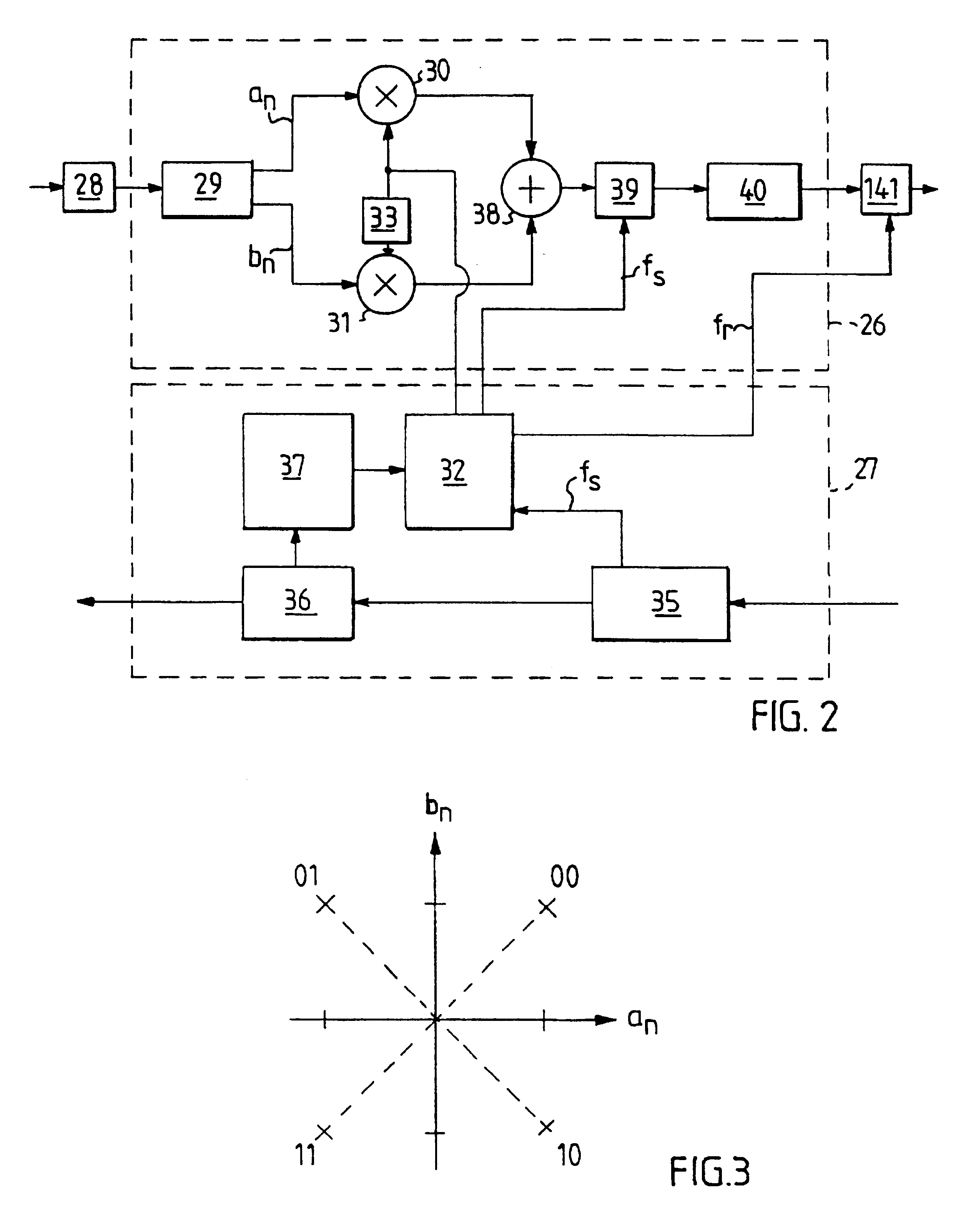
FIG. 12 shows a QPSK transmitter 126 according to the invention and relevant parts of the downstream receiver 27. (Here too, each subscriber can have one or more QPSK transmitters 126.) The QPSK transmitter 126 functions in the same way as the QPSK transmitter 26 in the preferred embodiment, with the addition of one phase compensation means 142. The phase compensation means 142 compensates for the effect of the protection period T.sub.g on the phase displacement of the signal, by restarting the wave form with a phase displacement specific to each symbol after each symbol. In this embodiment, neither grouping nor filtering of the groups with the same filter banks are needed, as all signals reach the receiver of the base station 1 with a phase displacement specific to each symbol.

FIG. 13 illustrates how each protection period T.sub.g displaces the phase by a phase angle .theta.. T.sub.g =I / 4 gives four possible phase displacements, the displacement given as:

.theta..sub.k =.theta..su...

third embodiment

According to the invention, the base station 1 can control the QPSK transmitter 26 of each subscriber so as to delay each transmission by a predefined time so that all transmissions will reach the receiver in the base station 1 at the same time and with a phase displacement specific to each symbol. In this embodiment no protection period is needed, and thus no phase error of the kind that arise in the preferred embodiment occurs, i.e. phase compensation or grouping and filtering of the groups using the same filter banks are not needed, as all signals reach the receiver of the base station with a phase displacement specific to each symbol.

The means 81 for computing the protection period T.sub.g and the means for computing the number and appearances of the phase displacements, both of which are found in the base station 1, then provide information for each QPSK transmitter 26 regarding the necessary delay of the upstream transmission. This information may, for example, be combined wit...


PUM


Abstract

A method and an apparatus transmit and receive information in a cable TV network including at least one base station connected to a branching cable network, branching from the base station to at least two subscribers, provided with transmitters. A unique carrier frequency is assigned to each of the subscriber's transmitters, the carrier frequencies being orthogonal. Signals from the subscriber's transmitters are transmitted simultaneously, received in the base station as a broadband signal, and separated using a common algorithm.

Description

The present invention concerns an apparatus and a method for sending and receiving information in a cable TV network.BACKGROUND AREAA cable TV network is a branched network in which a base station via an aerial receives TV signals from a satellite, or some other medium, and forwards the signals through a coaxial cable which branches to each individual user. The cable TV network is, second to the telephone network, the network that reaches the largest number of users. Therefore, it would be desirable co use the existing coaxial cable For new broadband services, such as the ordering of pay TV, interactive TV games, mail order services and so on. This requires the network to work in both directions so that the users can both receive information from the base station, called downstream signalling, and transmit information to the base station, called upstream signalling.These cable TV networks were originally designed for one-way communication through a coaxial cable, but have developed ...

Claims


Application Information

Patent Timeline
IPC IPC(8): H04H1/02H04N7/173H04H20/38H04H20/42H04H20/78H04H20/81H04H60/97
CPCH04H20/38H04H20/42H04H20/78H04H20/81H04H60/97H04N7/17309
Inventor JOHANSSON, ALBINHYLL, MATTIAS
Owner TELEFON AB LM ERICSSON (PUBL)
Why Eureka
Try Eureka