Dimensions in reactive distillation technology

Inactive Publication Date: 2002-12-31
TUNG PETER
View PDF21 Cites 11 Cited by
  • Summary
  • Abstract
  • Description
  • Claims
  • Application Information

AI Technical Summary

Benefits of technology

As taught in U.S. Pat. No. 5,961,815, hydrogen is fed at a point below the heavy petroliferous stock boiling above 400 deg F. where a reactive distillation arrangement generates lighter, more desirable products. Substantial quantities of desirable products will re-enter the cracking zone, producing more light ends and reducing overall reaction selectivity. Had a SRD unit been incorporated into the design, it will limit the reaction zone from re-cracking the desirable products, such as gasoline cut, from the reflux stream. This will greatly improve overall cracking selectivity and make better use of hydrogen, w

Problems solved by technology

1) Because of the free paths, both reactants and products can move freely into the reaction catalyst area or remain in the vapor/liquid main stream bulk area, resulting in higher residence time and lower reaction selectivity since desirable product(s) has more time to be converted to undesirable by-products.
2) Part of the product(s) leaving the reaction zone re-enters the reaction zone; either via vapor entering from the stripping zone below the reaction zone; or via liquid entering from the rectification zone above the reaction zone. Such undesirable product movem

Method used


Image

  • Dimensions in reactive distillation technology
  • Dimensions in reactive distillation technology
  • Dimensions in reactive distillation technology

Examples


Example

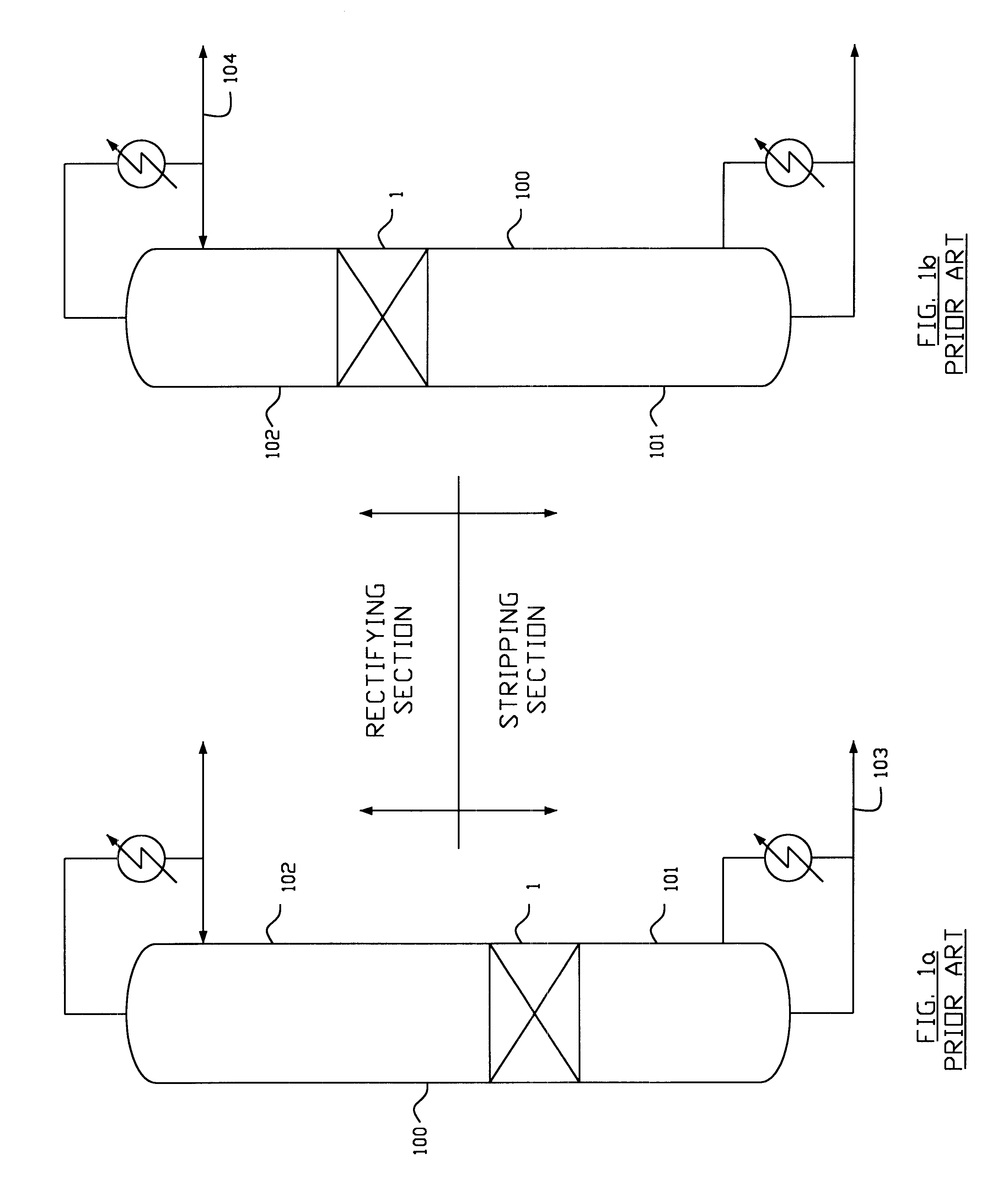
All reactive distillations conform to configurations shown in either FIG. 1a or FIG. 1b.

FIG. 1a shows a reaction zone (1) within a distillation column (100) where product(s) of reaction exits at the bottom of the reaction zone (1), is being distilled downward through the stripping section (101) and recovered in the bottom stream (103).

FIG. 1b shows a reaction zone (1) within a distillation column (100) where product(s) of reaction exits at the top of the reaction zone (1), is being distilled upward through the rectifying section (102) and recovered in the distillate stream (104). Higher fractionation improves vapor liquid contact within the reaction zone, which directionally increases conversion and improves selectivity.
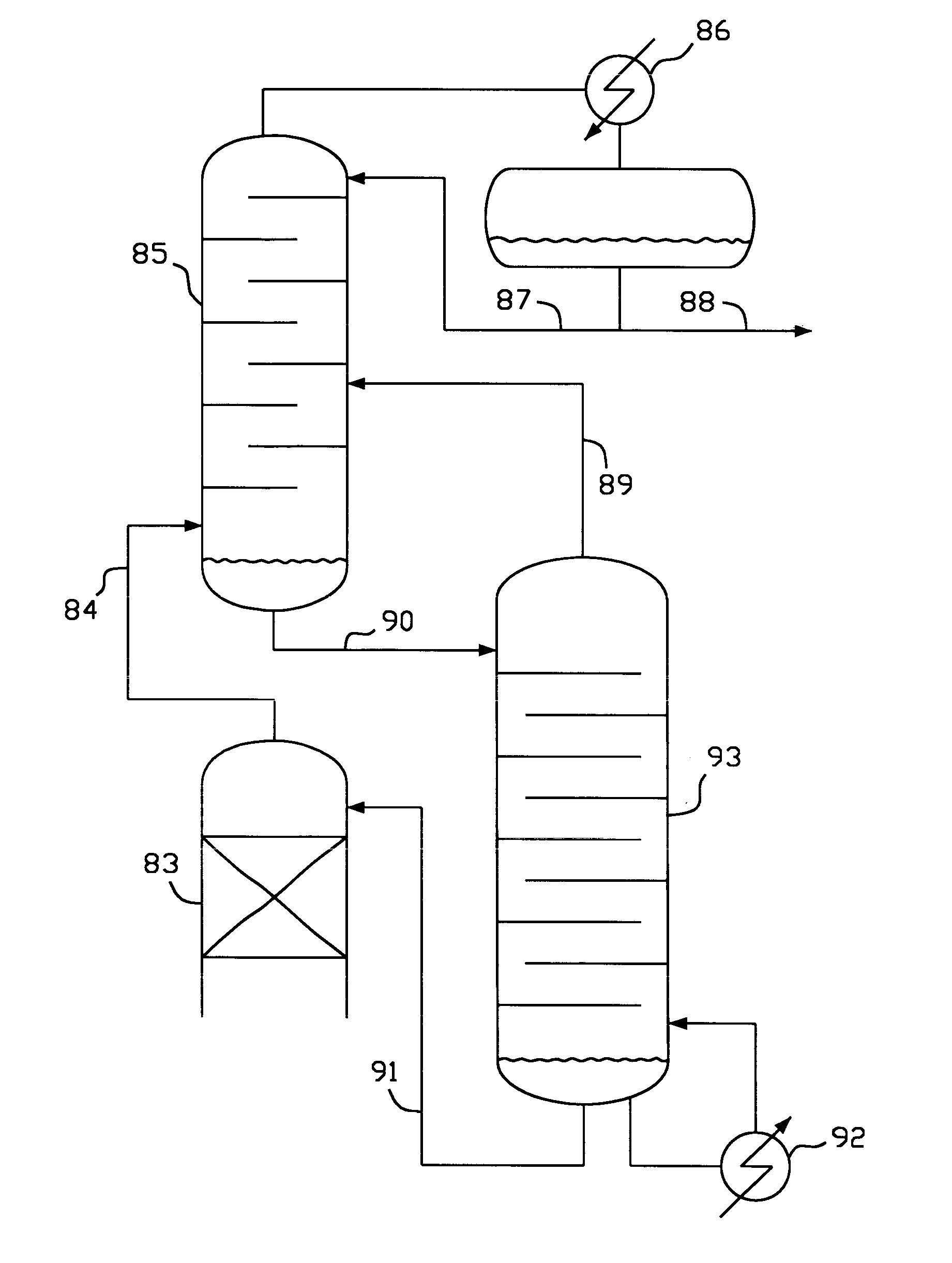
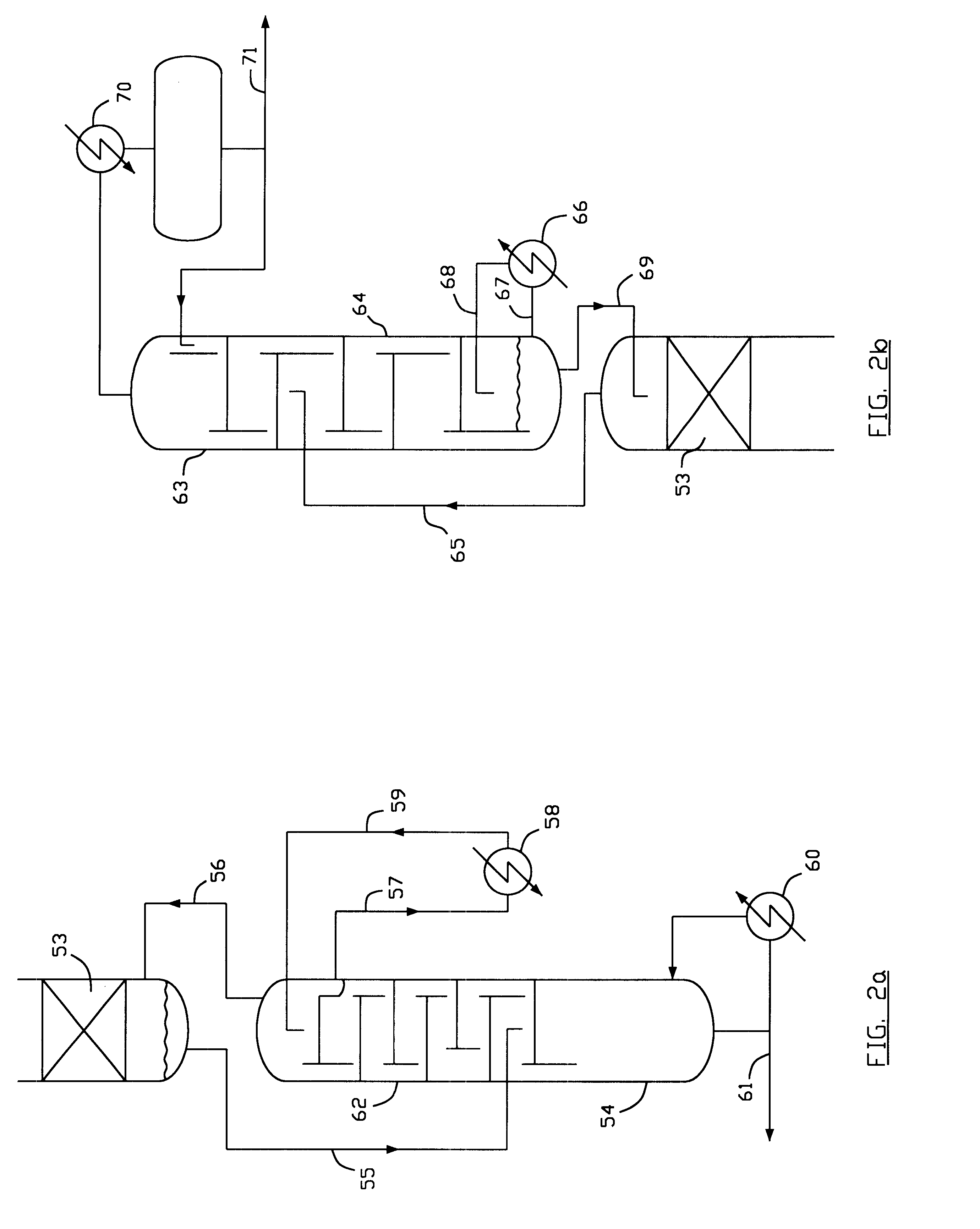

PUM


Abstract

A system for separating products from reactants within a reactive distillation column is revealed. Reaction products heavier than reactants are discouraged to re-enter the reaction zone by a rectifying section in between the reaction zone and the stripping section. Reaction products lighter than reactants are discouraged to re-enter the reaction zone by a stripping section in between the reaction zone and the rectifying section.

Description

1. Field of InventionThis invention relates to reactive distillation, specifically to improvements in reaction selectivity and conversion, resulting in reduced catalyst volume and capital costs requirement.2. Discussion of Prior ArtCombining chemical reaction and distillation in one unit operation has found wider acceptance despite intrinsic difficulty in pressure drop across reaction zone. U.S. Pat. No. 4,242,530 for example, taught the method of bundling catalysts in steel wire mesh to form bales, which are then placed inside a distillation column as reactive packing materials. These bales and other currently available reactive distillation packing structural arrangements are all designed to provide free paths for liquid / vapor counter current flow within the reaction zone.Two major drawbacks come with all existing arrangements:1) Because of the free paths, both reactants and products can move freely into the reaction catalyst area or remain in the vapor / liquid main stream bulk are...

Claims


Application Information

Patent Timeline
IPC IPC(8): B01J8/02B01D3/14B01D3/00
CPCB01D3/009B01D3/14B01J8/025Y10S203/06
Inventor TUNG, PETER
Owner TUNG PETER
Why Eureka
Try Eureka