

Method of plasma etching
- Summary
- Abstract
- Description
- Claims
- Application Information
AI Technical Summary
Benefits of technology
Problems solved by technology
Method used
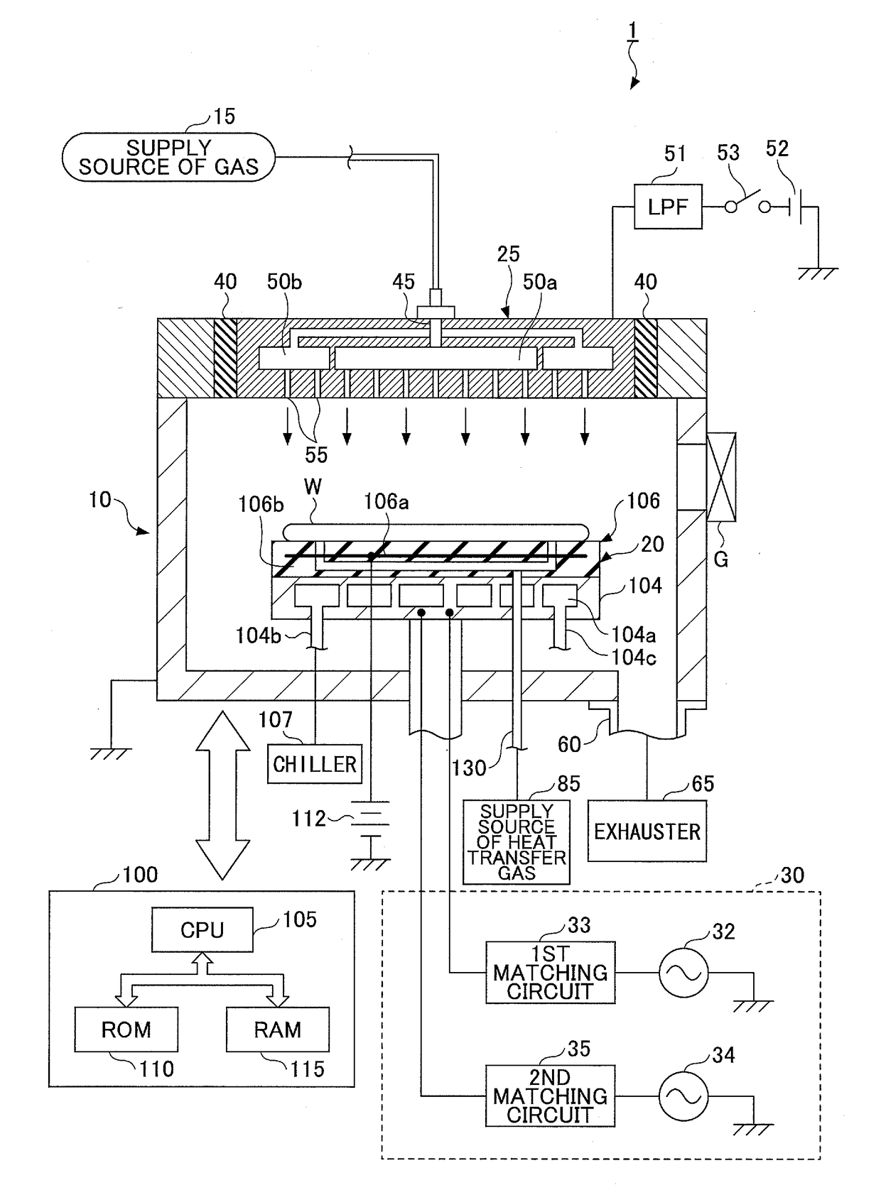
Image


Examples
first embodiment
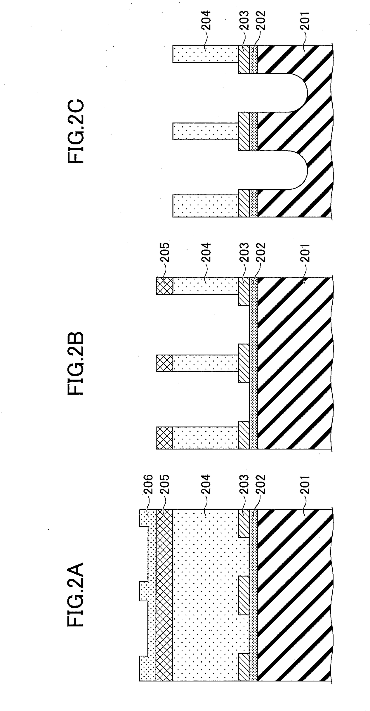
[0046]According to the first embodiment, the first high frequency power HF is intermittently applied in the etching process, to generate plasma from a process gas that includes fluorocarbon, and by the generated plasma, to etch the low-k film 201 with the TiN film 203 as the mask. This makes it possible to improve the selectivity of the TiN film 203 with respect to the low-k film 201. Consequently, generation of encroachment can be prevented.
[0047]FIG. 4 is a diagram for illustrating waveforms of the high frequency power according to the first embodiment.
[0048]As illustrated in FIG. 4, in the etching process in the method of plasma etching according to the first embodiment, the first high frequency power HF is repeatedly turned on and off alternately to apply the first high frequency power HF intermittently. On the other hand, the second high frequency power LF is maintained to be turned on to apply the second high frequency power LF continuously. In other words, the first high freq...
second embodiment
[0095]Next, the method of plasma etching in the second embodiment will be described. In the first embodiment, the method of plasma etching has been described in which the first high frequency power HF is intermittently applied. In contrast to this, in the method of plasma etching in the second embodiment, the first high frequency power HF is intermittently applied, and in addition, the second high frequency power LF is also intermittently applied synchronized with the first high frequency power HF.
[0096]FIG. 8 is a diagram illustrating waveforms of the high frequency power according to the second embodiment.
[0097]As illustrated in FIG. 8, in the etching process in the method of plasma etching according to the second embodiment, the first high frequency power HF is repeatedly turned on and off alternately to apply the first high frequency power HF intermittently. Also, synchronized with the first high frequency power HF, the second high frequency power LF is repeatedly turned on and ...
PUM
 Abstract
Description
Claims
Application Information