
Method of manufacturing bonded magnets of rare earth metal, and bonded magnet of rare earth metal

Inactive Publication Date: 2002-12-31
SEIKO EPSON CORP
View PDF9 Cites 40 Cited by
  • Summary
  • Abstract
  • Description
  • Claims
  • Application Information

AI Technical Summary

Benefits of technology

[5] A mixture comprising at least two compositions of the above-described paragraph [1] to [4]. In this case, the obtained magnet can possess both of the benefits of the mixed magnetic powders, namely, a bonded magnet having superior magnetic properties can be readily obtained.
Due to an appropriate composition of the magnetic powder, a higher content of the magnetic powder and other specific factors, the rare-earth bonded magnet of the present invention can exhibit superior magnetic properties even if it is an isotropic magnet or an anisotropic magnet.

Problems solved by technology

In compaction molding, however, the variety of moldable magnet shapes is restricted, and productivity is low.
In injection molding, however, since high fluidity is required of the melted compound, a large amount of binder resin must be added.
The binder resin content in the obtained magnet therefore increases, which results in low magnetic properties.
This measure may, however, be restricted from matter concerning the composition, properties and the like of the binder resin, and thermostability and oxidation resistance of the magnetic powder.
As a result, the advantages of extrusion molding cannot be sufficiently exhibited.
Additionally, rare-earth bonded magnets having plate or thinner shapes, which generally have low strength, are readily deformed by the action of gravity during the manufacturing process, and in such cases, the obtained magnets exhibit lowered dimensional accuracy.

Method used


Image

  • Method of manufacturing bonded magnets of rare earth metal, and bonded magnet of rare earth metal
  • Method of manufacturing bonded magnets of rare earth metal, and bonded magnet of rare earth metal

Examples


examples 14 and 15

Rare-earth bonded magnets were manufactured in a manner similar to Examples 1 to 13 above, except that the mixtures having the compositions shown in Table 1 were directly fed into the ram extruder, respectively.

The composition, density, void ratio, roundness and straightness (indexes representing dimensional precision), and other properties of each magnet manufactured based on the conditions shown in the tables are shown in Tables 4, 5, 6 and 7.

Roundness=(Maximum Outer Diameter-Minimum Outer Diameter).times.1 / 2 [mm] (1)

Further, the item "straightness" in Tables 4 to 7 is an index for dimensional accuracy of a sample, and was determined as follows. A sample cut into a length of 100 mm was placed on a horizontally flat surface, gaps generated by curvature and waviness of the sample between the sample and the flat surface were measured, and the maximum of the measured values was regarded as the straightness of the sample. Samples having a smaller straightness value are more ideally str...


PUM

PropertyMeasurementUnit
Temperatureaaaaaaaaaa

Abstract

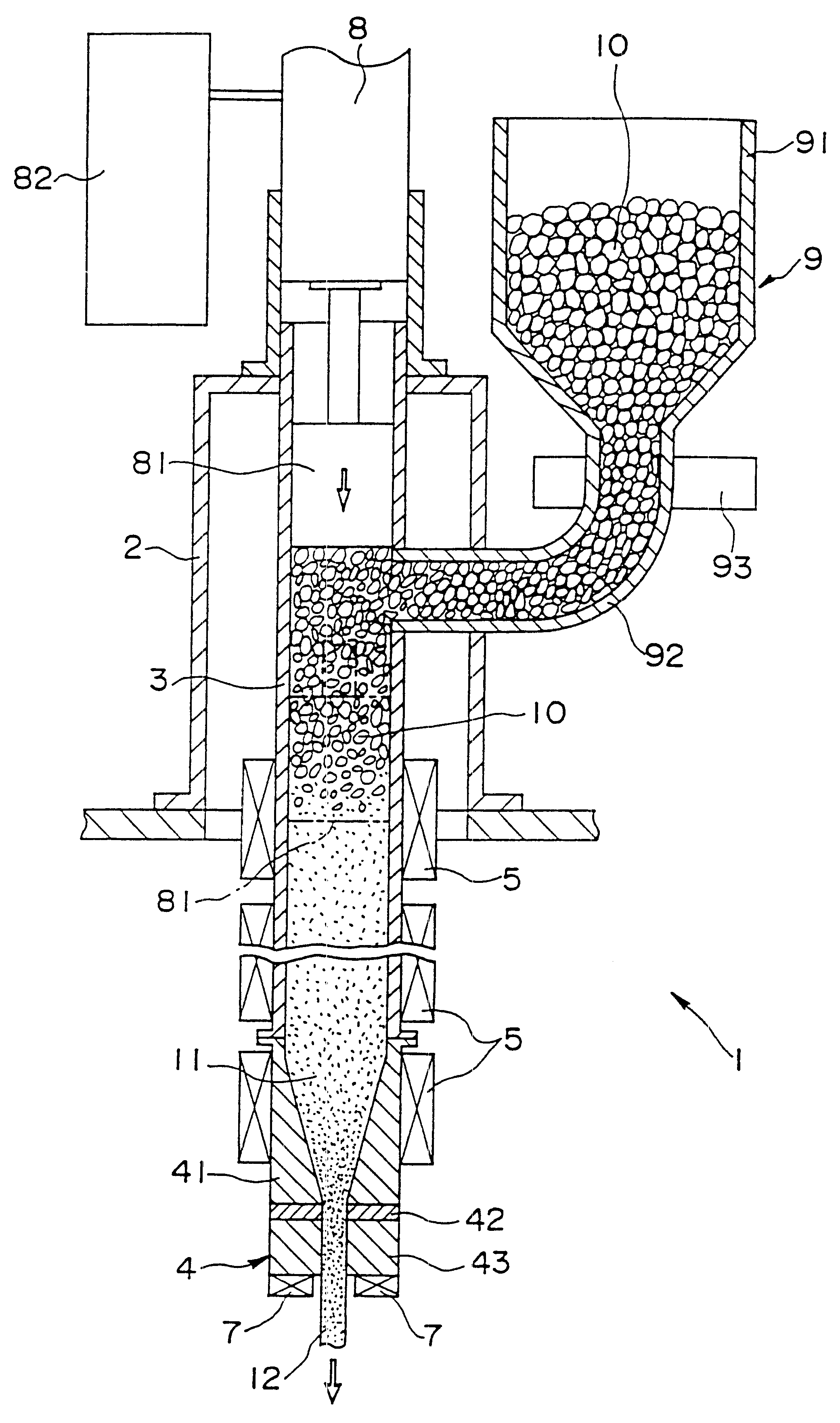
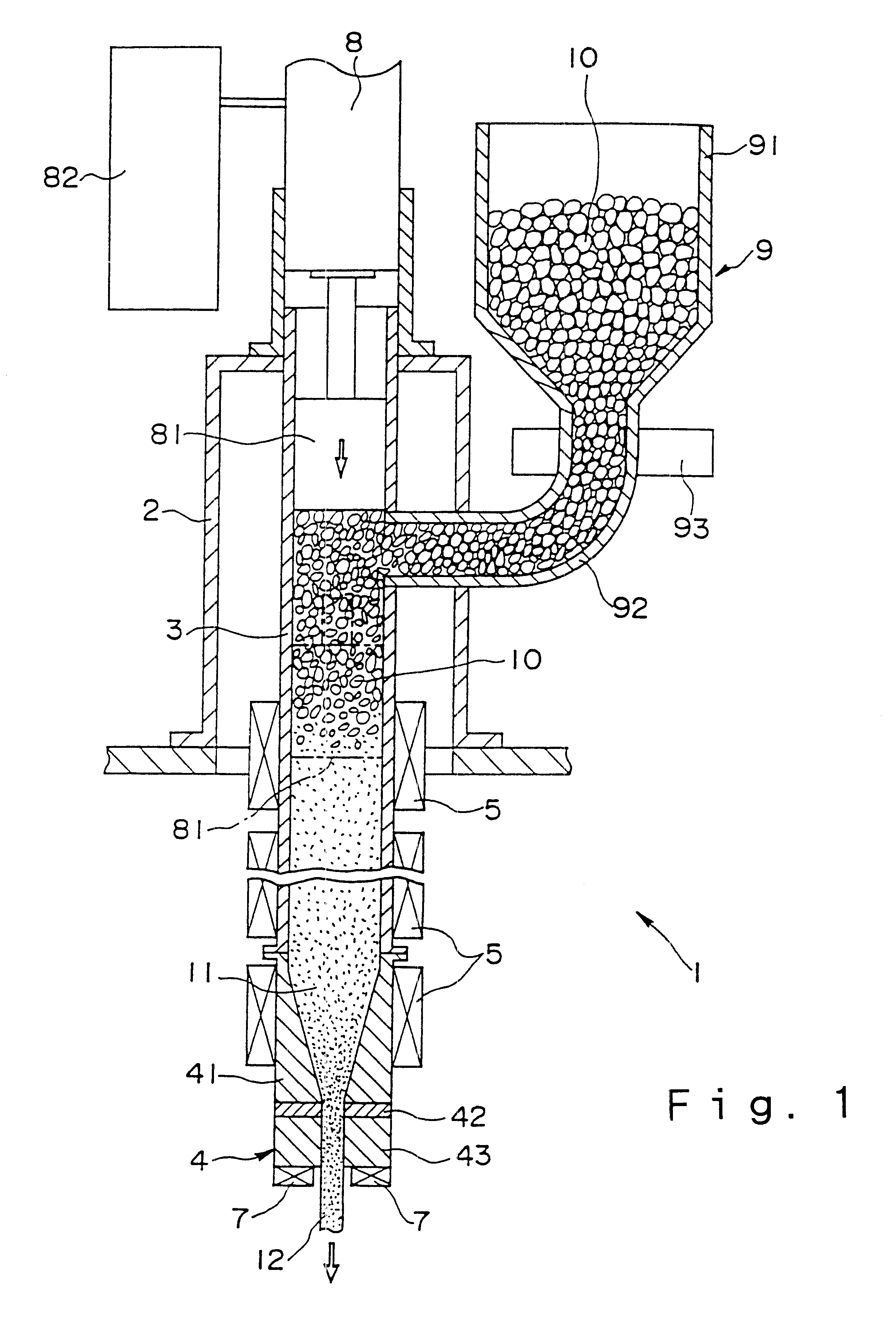
The present invention provides a method for manufacturing a rare-earth bonded magnet as follows: A compound 10, prepared by pelletizing a kneaded mixture of a rare-earth-bonded-magnet composition containing a rare-earth magnet powder, a binder resin and an antioxidant, is stored in a hopper 91, and fed into a cylinder 3 through a feeding pipe 92. Meanwhile, piston 81 is extended by driving an oil-hydraulic cylinder 8, and moved downward to compact the compound 10 fed into the cylinder 3 while gradually transferring the compound downward inside the cylinder 3. The cylinder 3 and a heating portion 41 are heated by heaters 5, the compound 10 passing therethrough is heated to become a melted material 11, and the melted material 11 is continuously extruded out from a die 4 in the downward-vertical direction, and is then cooled and solidified when passing through a tip portion 43, thus obtaining a molded body 12 of a rare-earth-bonded-magnet.

Description

The present invention relates to a method for manufacturing a rare-earth bonded magnet, and a rare-earth bonded magnet manufactured according to the method.In general, a rare-earth bonded magnet is manufactured by molding a mixture or a kneaded mixture (compound) of a rare-earth magnetic powder and a binder resin (organic binder) into a desired magnet shape. For molding, compaction molding, injection molding or extrusion molding is employed.In compaction molding, such a compound is placed into a mold and press-molded to obtain a green compact, and the compact is then heated to harden a thermosetting resin contained as a binder resin in the compound, thus manufacturing a bonded magnet. Since compaction molding is applicable to a composition including a smaller amount of the binder resin than that for other molding methods, the resin content in the obtained magnet can be reduced, and therefore, magnetic properties of the obtained magnet can be advantageously enhanced. In compaction mo...

Claims


Application Information

Patent Timeline
IPC IPC(8): B22F3/20C22C1/04H01F1/057H01F41/02H01F1/059H01F1/032H01F1/055B22F3/22
CPCB22F3/20C22C1/0441H01F1/0558H01F1/0578H01F1/059H01F41/0253H01F41/0266B22F3/227Y10T428/1355B22F2998/00Y10S428/90Y10S264/58B22F3/22C22C32/0094H01F41/02
Inventor AKIOKA, KOJISHIRAI, HAYATOIKUMA, KEN
Owner SEIKO EPSON CORP
Learn More