

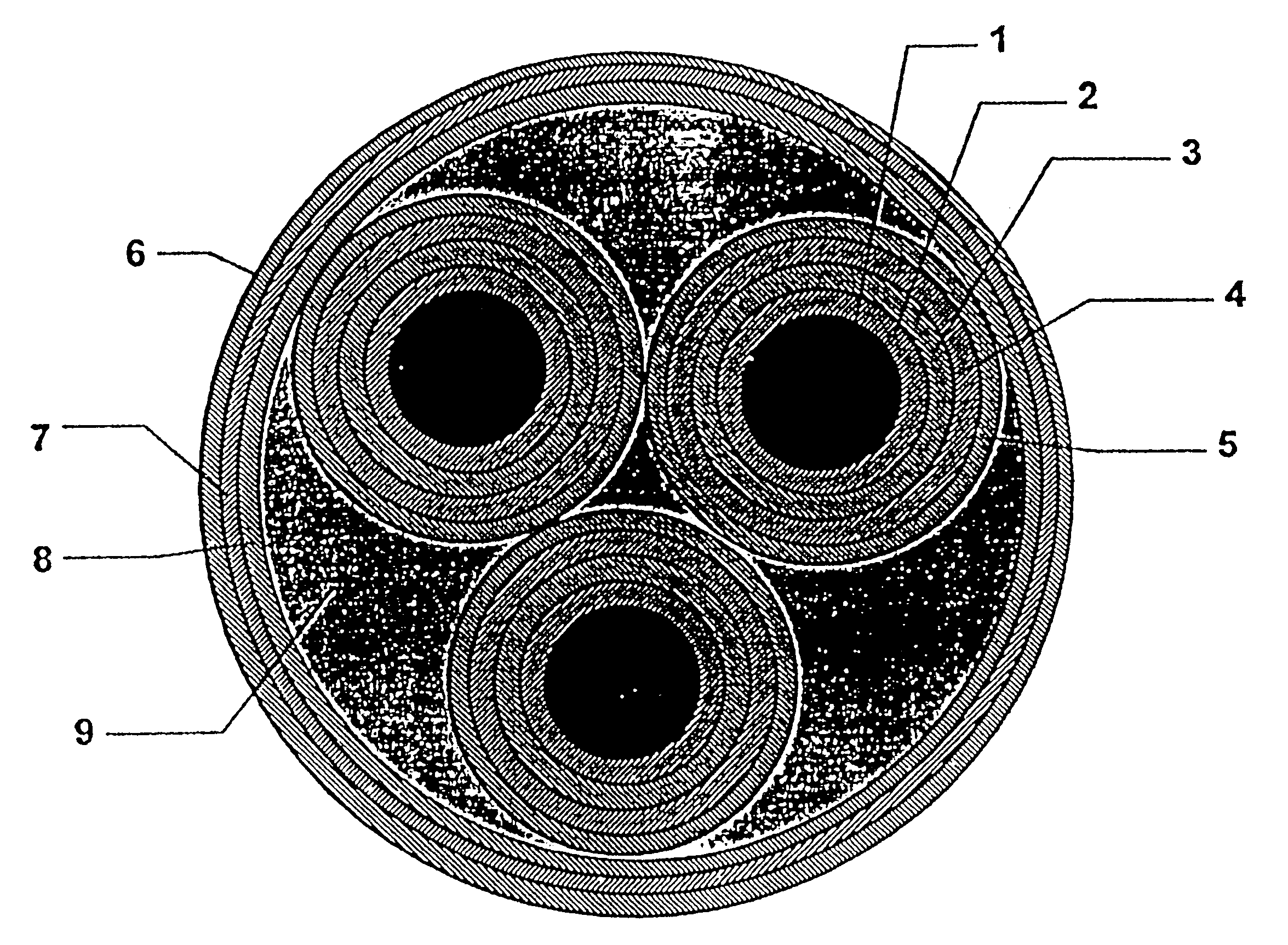
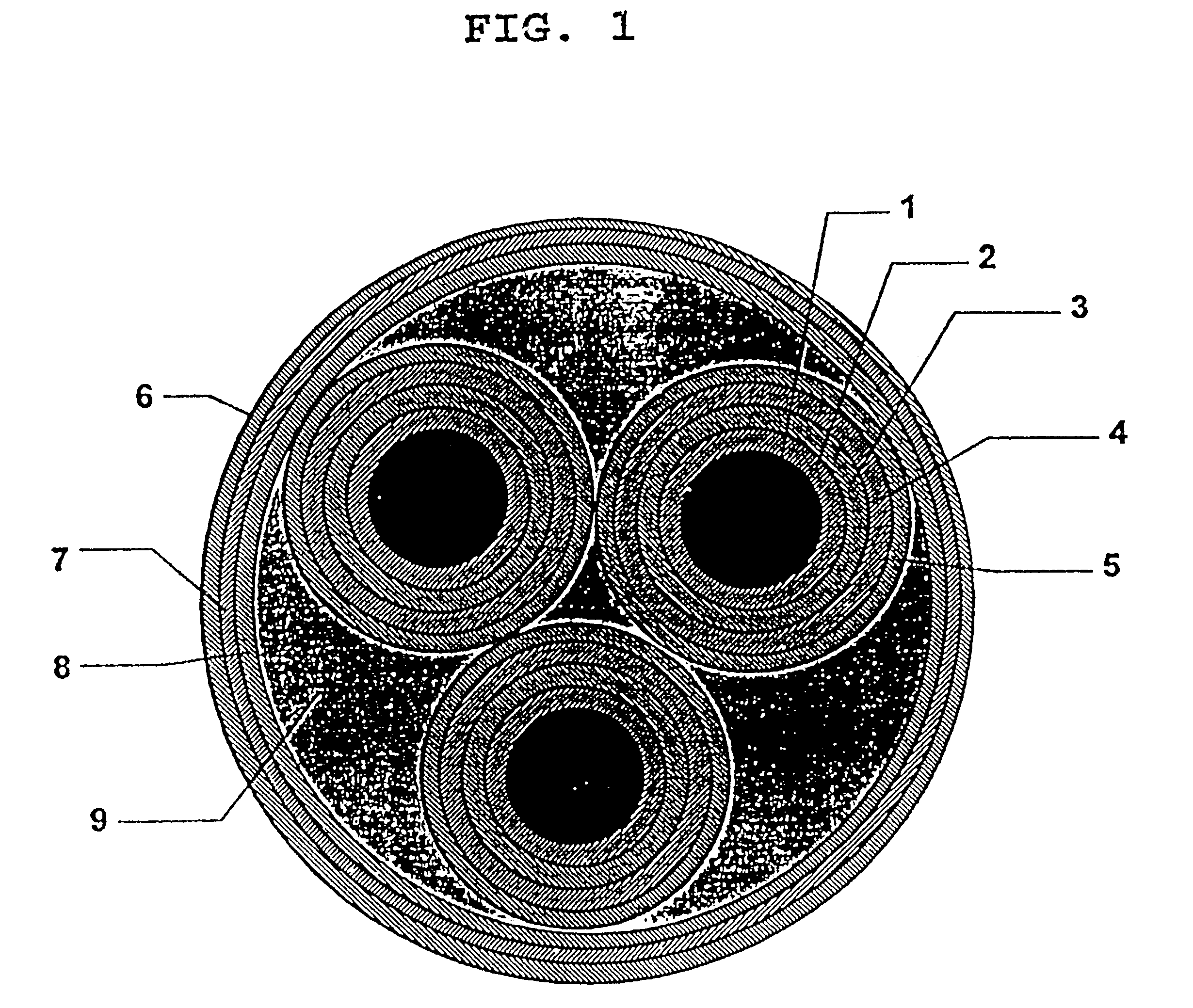
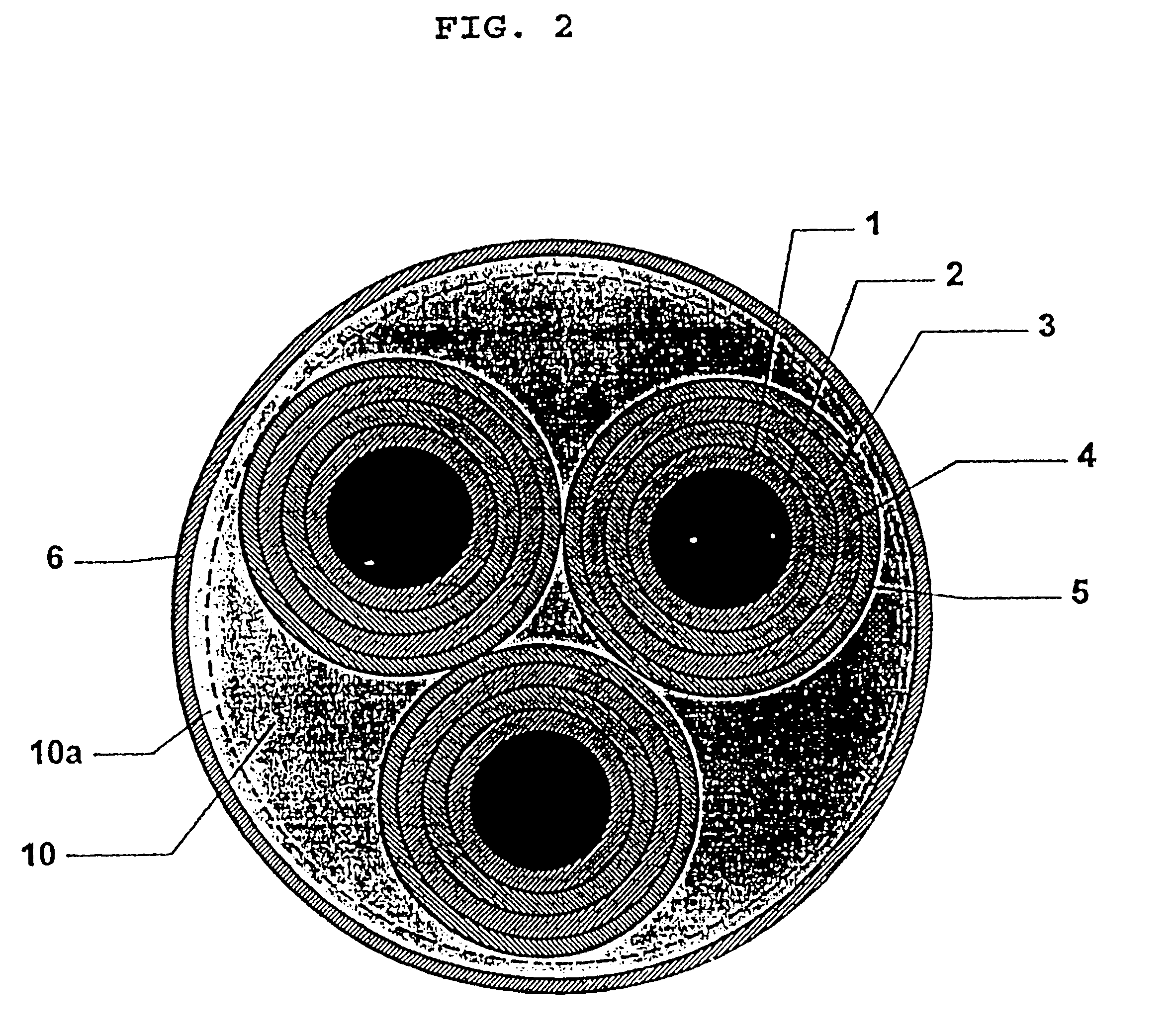
Cable with impact-resistant coating
a technology of impact-resistant coating and cable, which is applied in the direction of plastic/resin/waxes insulators, organic insulators, conductors, etc., can solve the problems of increasing the weight of the cable, reducing the insulating capacity of this coating, and variable electrical gradient of the insulating coating
- Summary
- Abstract
- Description
- Claims
- Application Information
AI Technical Summary
Benefits of technology
Problems solved by technology
Method used
Image

Examples
example 2
Impact Strength Tests
In order to evaluate the impact strength of the cables prepared according to Example 1, impact tests were carried out on the cable with subsequent evaluation of the damage. The effects of the impact were evaluated both by means of visual analysis of the cable and by means of measuring the variation in peel strength of the layer of semiconductive material at the point of impact. The impact test is based on the French standard HN 33-S-52, which provides for an energy of impact on the cable of about 72 joules (J), which is obtained by dropping a 27 kg weight from a height of 27 cm. For the present test, such energy of impact has been produced by a 8 kg weight dropped from a height of 97 cm. The impact-end of the weight is provided with a V-shaped rounded-edge (1 mm curvature radius) punching head. For the purposes of the present invention, the impact strength was evaluated on a single impact. For samples 6-12, the test was repeated a second time at a distance of ab...
example 3
Impact Strength Comparison Test with Armored Cable
Cable no. 10 has been tested versus a conventional armored cable, in order to verify the impact strength efficiency of the expanded coating layer.
The armored cable has the same core as cable no. 10 (i.e. a multi-wire conductor about 14 mm in thickness coated with a layer of 0.5 mm of semiconductive material, a layer of 3 mm of an insulating mixture based on EPR and a further layer of 0.5 mm of "easy stripping" semiconductive material based on EVA supplemented with carbon black, for a total core thickness of about 22 mm). Said core is encircled, from the inside towards the outside of the cable by:
a) a layer of rubber-based filling material of about 0.6 mm thickness;
b) a sheath of PVC of about 0.6 mm thickness;
c) 2 armoring steel tapes of about 0.5 mm thickness each;
d) an outer sheath of MDPE of about 2 mm thickness.
For the comparison test, a dynamic machine of the "falling weight" type (CEAST, mod. 6758) has been employed. Two sets of...
PUM
| Property | Measurement | Unit |
|---|---|---|
| Fraction | aaaaa | aaaaa |
| Fraction | aaaaa | aaaaa |
| Fraction | aaaaa | aaaaa |
Abstract
Description
Claims
Application Information