Hybrid synchronous machines comprising permanent magnets and excitation windings in cylindrical element slots

a technology of excitation windings and synchronous machines, which is applied in the direction of windings, magnetic circuit rotating parts, magnetic circuit shapes/forms/construction, etc., can solve the problems of inability to control the operation of permanent magnet machines in constant power mode, poor efficiency, etc., and achieve the effect of high efficiency of permanent magnet machines

Inactive Publication Date: 2003-01-21
GENERAL ELECTRIC CO
View PDF30 Cites 55 Cited by
  • Summary
  • Abstract
  • Description
  • Claims
  • Application Information

AI Technical Summary

Benefits of technology

It would therefore be desirable to have a durable machine that further combines the advantages of the excitation control of wound field machines and the advantages of higher efficiency of permanent magnet machines.

Problems solved by technology

Permanent magnet machines are not easily regulated.
Operation of permanent magnet machines in constant power mode can be a problem because low power factor operation is forced through flux weakening methods to reduce voltage at light loads or to minimize inverter ratings.
As a result, the machine terminal voltage becomes load dependent, efficiency suffers, and, at partial loads, the magnetic field source is underutilized.
Machines wound with excitation windings ("wound field machines") can be regulated over a wide range of loads, but wound field machines experience winding losses that decrease machine efficiency.
Additionally, windings and excitation sources for wound field machines are sized to support the maximum requirements and thus are often expensive and under-utilized.
Automotive alternators operate at low magnetic and mechanical stress levels and often include complex and fragile multiple pole configurations.

Method used


Image

  • Hybrid synchronous machines comprising permanent magnets and excitation windings in cylindrical element slots
  • Hybrid synchronous machines comprising permanent magnets and excitation windings in cylindrical element slots
  • Hybrid synchronous machines comprising permanent magnets and excitation windings in cylindrical element slots

Examples


Embodiment Construction

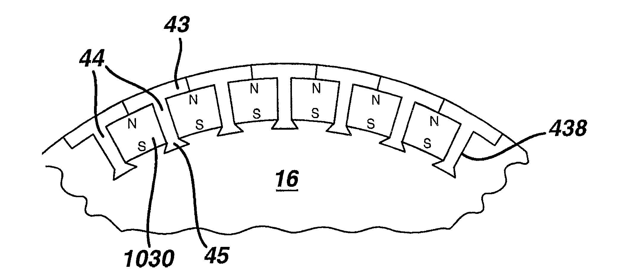
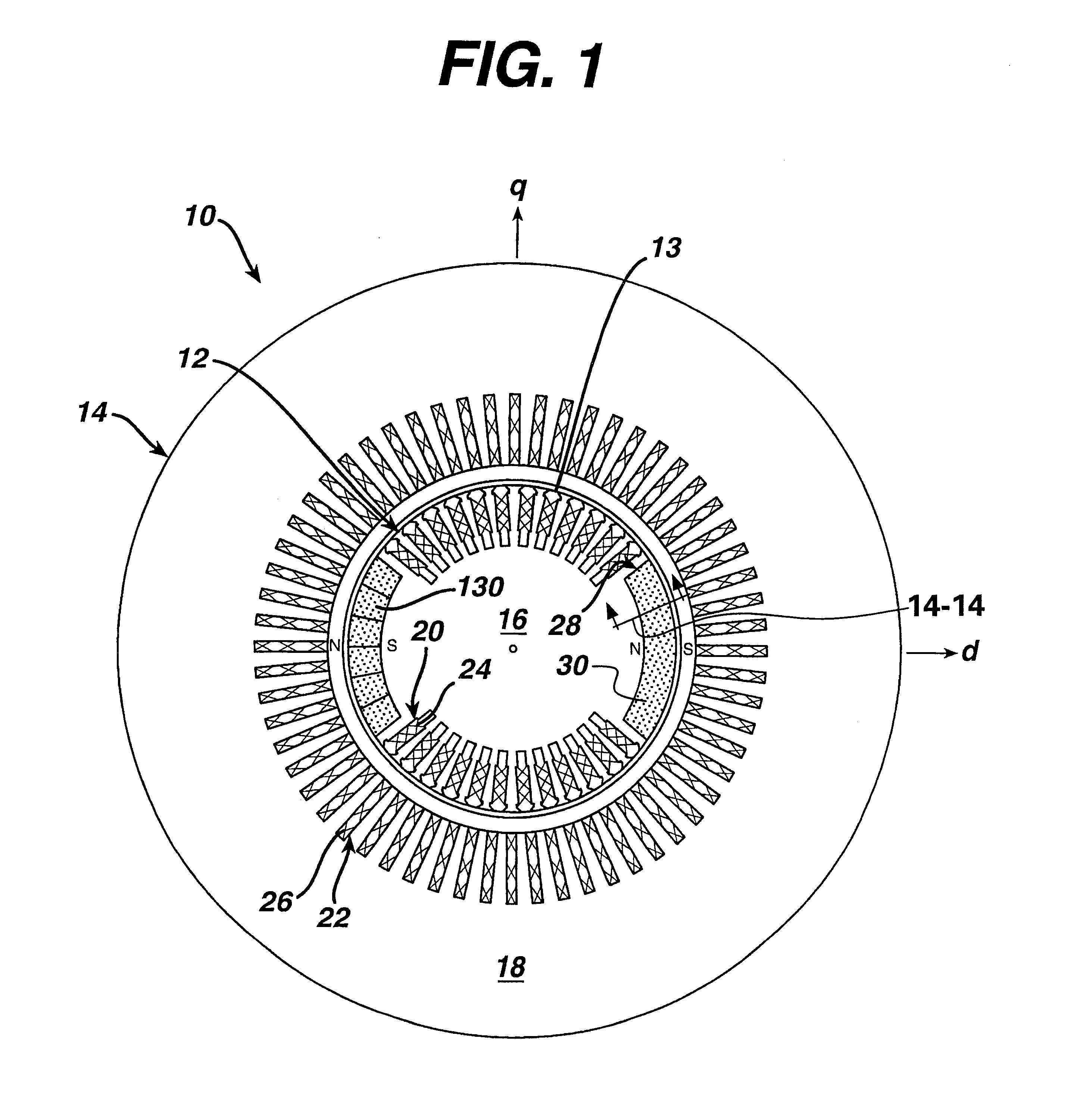
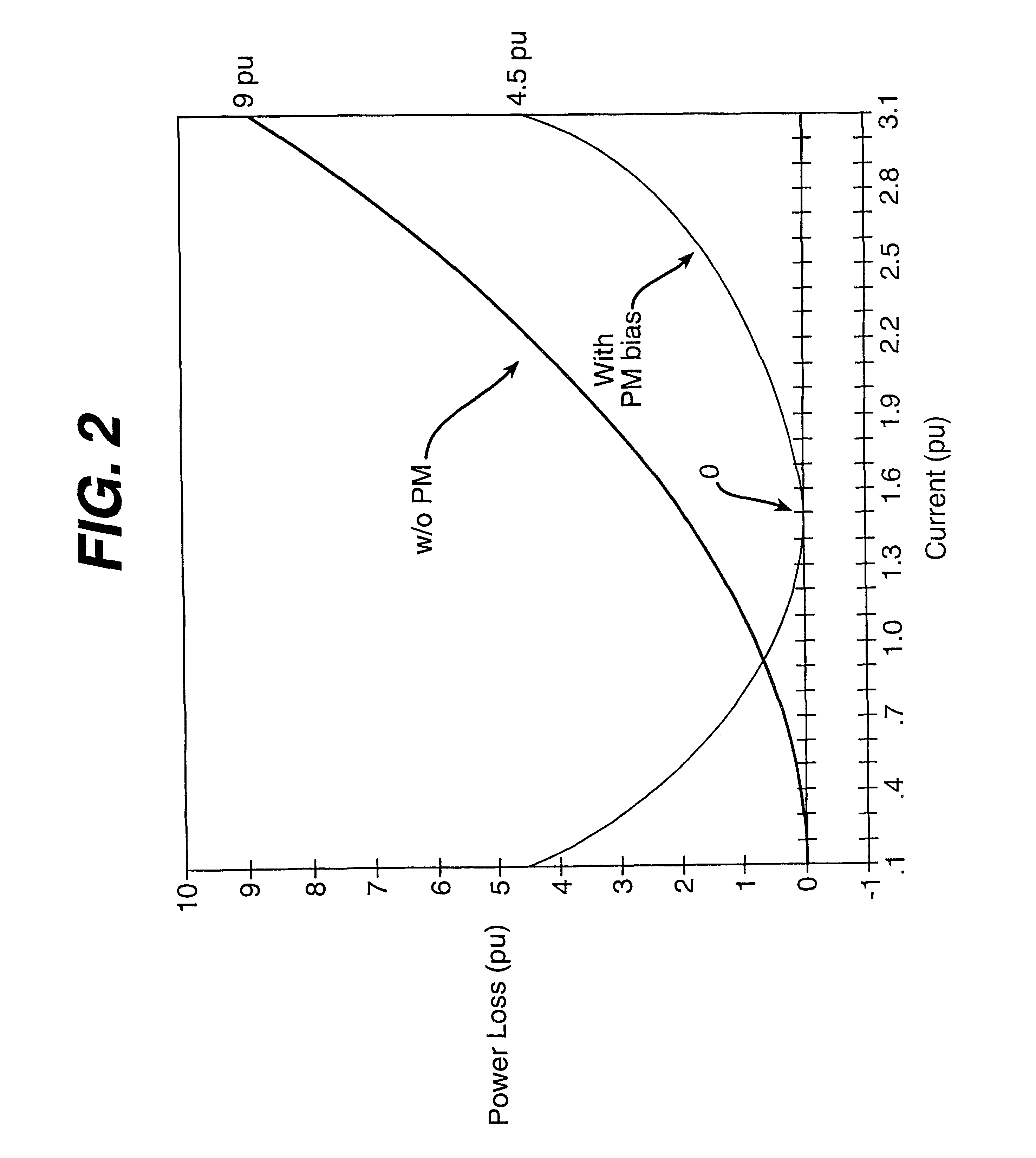
FIG. 1 is a sectional view of a hybrid synchronous machine according to one embodiment of the present invention, FIG. 2 is a graph of excitation winding power loss versus excitation current illustrating expected improved characteristics of the present invention as compared with conventional wound field machines, and FIGS. 3-6 are sectional views of a rotors for hybrid synchronous machines according to other embodiments of the present invention.

In the embodiments of FIGS. 1 and 3-6, a hybrid synchronous machine comprises a cylindrical element having slots; excitation windings situated in at least some of the slots; and permanent magnets 30 situated in at least some of the slots. In an embodiment wherein the cylindrical element comprises a rotor 12, slots (and optional slots 28) can be used with excitation windings 24. In an embodiment wherein the cylindrical element comprises a stator 14, slots 22 can be used with excitation windings 26. The present invention is shown with the excita...


PUM


Abstract

A hybrid synchronous machine includes a cylindrical element having slots; excitation windings situated in at least some of the slots; and permanent magnets situated in at least some of the slots, the permanent magnets comprising radially magnetized permanent magnets.

Description

The invention relates generally to synchronous machines having round or salient pole rotors.Most synchronous machines are designed to include either permanent magnets or excitation windings (fed by a regulated source) to provide MMF (magnetomotive force) that provides the magnetic flux for machine operation. The permanent magnets or excitation windings can be situated on either the rotor or the stator. For rotor-based embodiments, excitation power is brought through either a set of collectors (slip rings) or a brushless system that uses a small ("inside-out") synchronous machine with a stator excitation source.Permanent magnet machines are not easily regulated. Operation of permanent magnet machines in constant power mode can be a problem because low power factor operation is forced through flux weakening methods to reduce voltage at light loads or to minimize inverter ratings. As a result, the machine terminal voltage becomes load dependent, efficiency suffers, and, at partial load...

Claims


Application Information

Patent Timeline
Patent Type & Authority Patents(United States)
IPC IPC(8): H02K1/22
CPCH02K21/042
Inventor SHAH, MANOJ RAMPRASADKLIMAN, GERALD BURT
Owner GENERAL ELECTRIC CO
Why Eureka
Try Eureka