Touch panel with improved optical performance

a touch panel and optical performance technology, applied in the field of input devices, can solve the problems of capacitive touch screen damage, poor display characteristics, easy damage of resistive touch screen, etc., and achieve the effect of improving the optical performance of the touch panel

Inactive Publication Date: 2003-01-28
L 3 COMM CORP
View PDF26 Cites 57 Cited by
  • Summary
  • Abstract
  • Description
  • Claims
  • Application Information

AI Technical Summary

Problems solved by technology

However, it is the differences in the way that the various types of touch screens operate that causes a designer to use one type of touch screen over another for a particular application.
Disadvantageously, however, resistive touch screens can be easily damaged and exhibit poor display characteristics (particularly in sunlight).
Capacitive touch screens also provide high touch point density and low cost, but capacitive touch screens can be easily damaged, must be calibrated due to large temperature changes, and cannot be operated with a gloved hand.
However, surface acoustic wave touch screens typically exhibit the highest cost and can be falsely triggered by noise, wind, transmission signals, and insects.
Touch screens that use light beam interruption, typically called infrared touch screens, are relatively expensive.
Advantageously however, they have no touch sensitive overlay to be damaged, exhibit high touch point density, can be operated with heavy gloves, exhibit good immunity to most false trigger sources, and are extremely rugged and weather sealable.
Although these advantages typically make infrared touch screens the most suitable type of touch screen to use in outdoor applications, high ambient light conditions, such as direct sunlight, can cause an infrared touch screen to malfunction.
It can be seen that each type of touch screen exhibits some disadvantage which makes it not well suited for outdoor use, particularly in high ambient light conditions.
This overlay screen suffers in outdoor applications, and particularly in sunlight, for various reasons.
First, the typical reflectance of such overlay screens is about 25%, making the underlying display difficult to read.
Second, such overlay screens allow most of the infrared radiation from sunlight to be absorbed by the underlying liquid crystal display, and this radiation can cause solar thermal loading of the display which lead to display malfunction.
Third, the materials used for such overlay screens tend to deteriorate rapidly from exposure to the ultraviolet rays of the sun.
Fourth, the top layer touched by users is easily scratched or damaged, thus requiring the whole touch panel to be replaced.

Method used


Image

  • Touch panel with improved optical performance
  • Touch panel with improved optical performance
  • Touch panel with improved optical performance

Examples


Embodiment Construction

One or more specific embodiments of the present invention will be described below. In an effort to provide a concise description of these embodiments, not all features of an actual implementation are described in the specification. It should be appreciated that in the development of any such actual implementation, as in any engineering or design project, numerous implementation-specific decisions must be made to achieve the developers' specific goals, such as compliance with system-related and business-related constraints, which may vary from one implementation to another. Moreover, it should be appreciated that such a development effort might be complex and time consuming, but would nevertheless be a routine undertaking of design, fabrication, and manufacture for those of ordinary skill having the benefit of this disclosure.

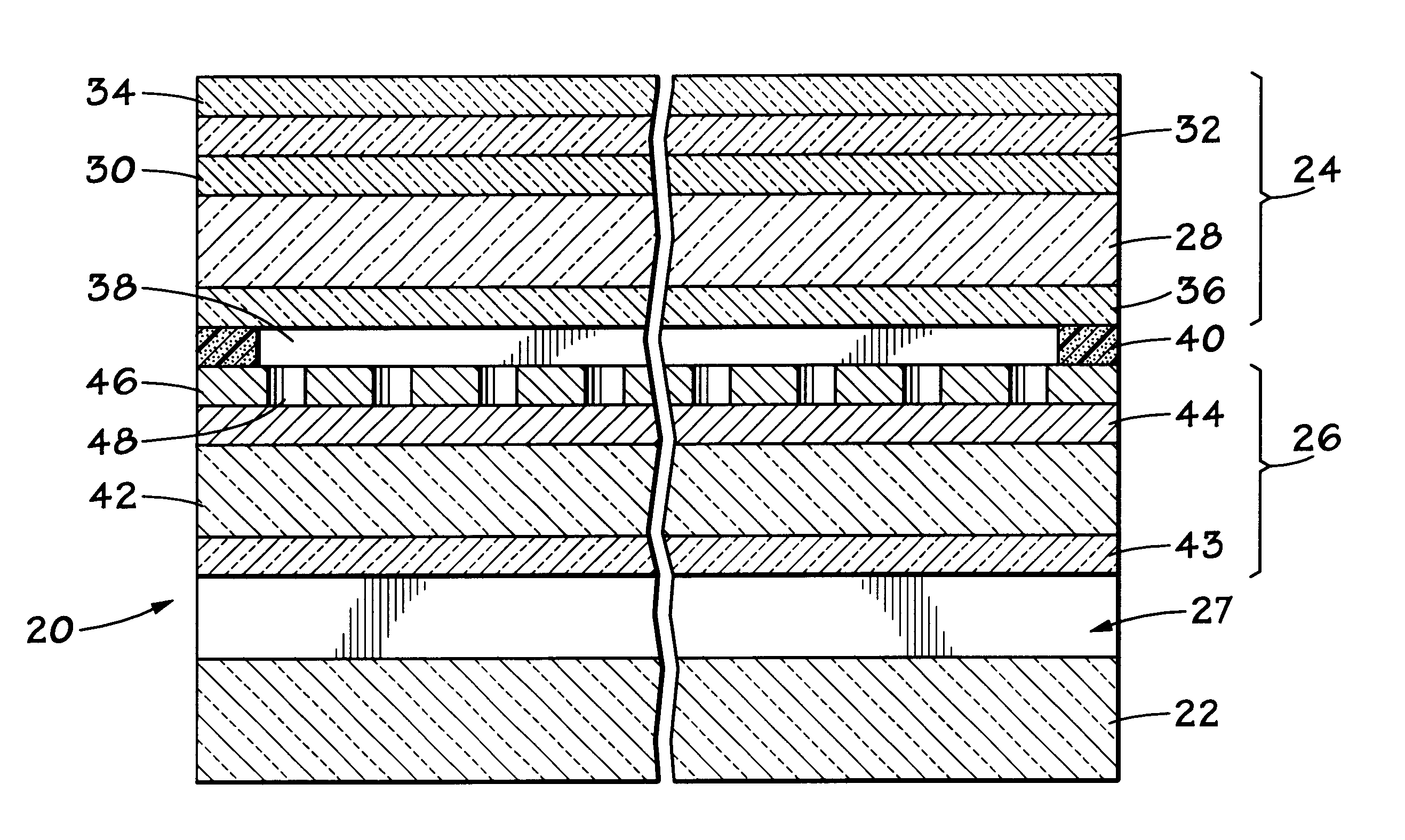
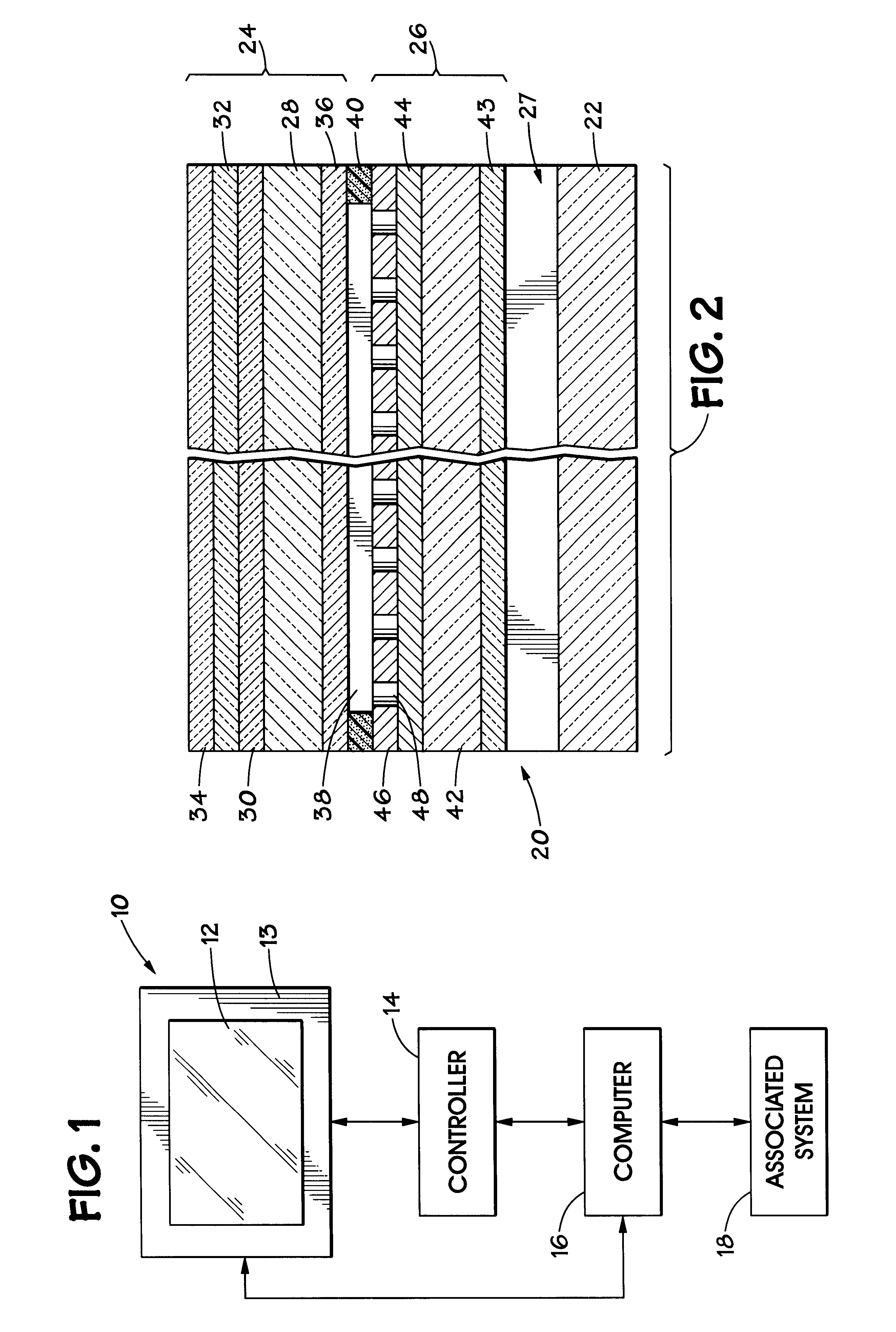
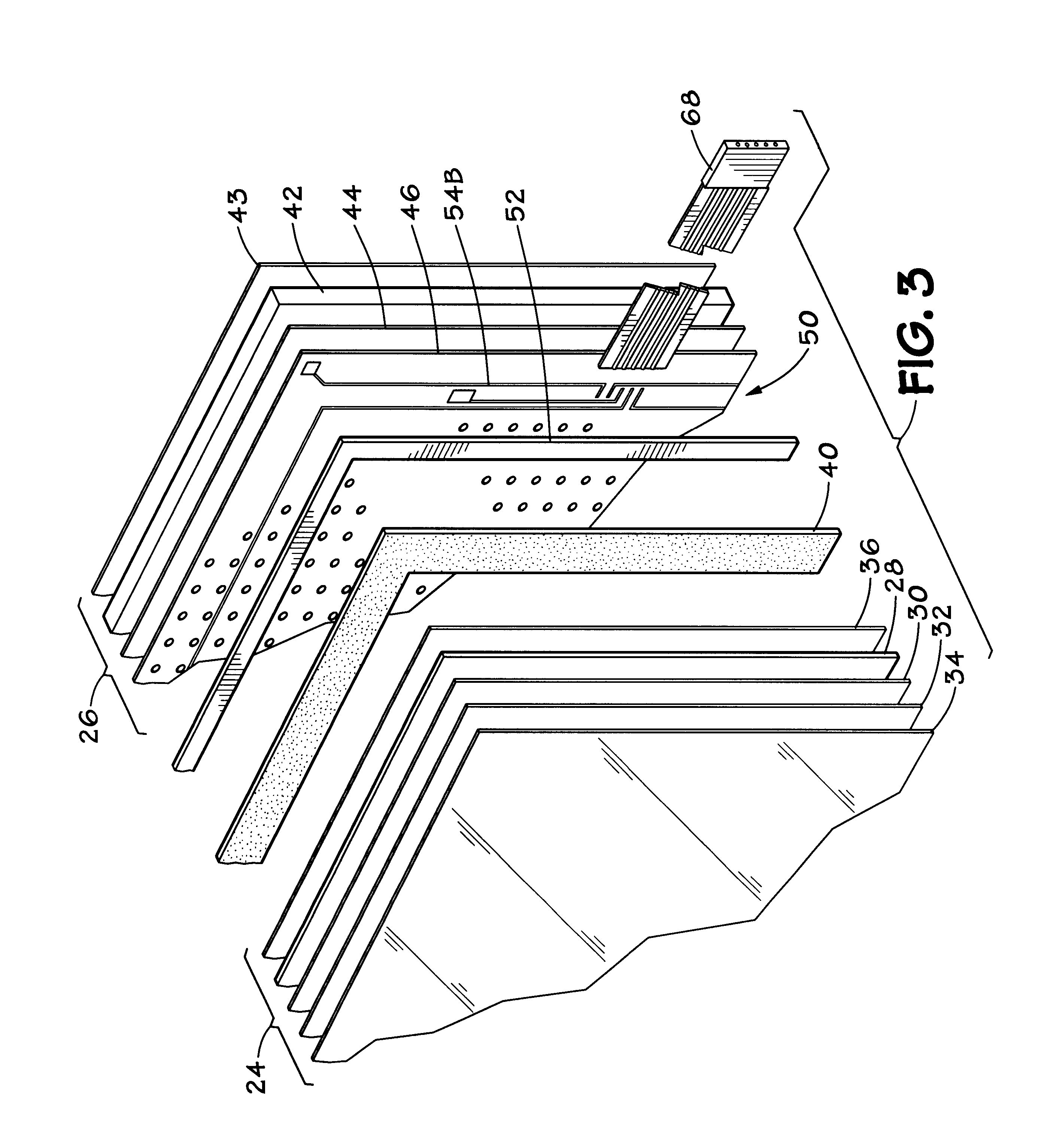
Turning now to the drawings, and referring initially to FIG. 1, a touch screen display system is illustrated and generally designated by a reference numeral 10....


PUM

PropertyMeasurementUnit
reflectanceaaaaaaaaaa
thicknessaaaaaaaaaa
reflectivityaaaaaaaaaa

Abstract

Sunlight can damage a conventional touch screen display and cause the display to be quite difficult to read. Furthermore, conventional touch screen displays are easily damaged, and, once damaged, the entire touch screen is replaced. To address these concerns, a touch panel includes anti-reflective coatings on the surfaces of the top plate and the base plate that are open to the air. These coatings substantially reduce reflections and make the touch screen easier to read in direct sunlight. In particular, the anti-reflective coating used on the upper surface of the base plate is dielectric in nature to reduce reflectivity even further. This dielectric coating includes openings to an underlying conductive layer so that an electrical contact is made when a user deflects the top plate into the base plate. Also, the top plate may be detachably coupled to the base plate, advantageously by double stick adhesive tape, so that only the top plate is replaced when damaged. Furthermore, a resistive voltage divider may be fabricated on the base plate. The resistive voltage divider may include a substantially continuous strip of resistive material disposed on the conductive layer of the base plate, and a plurality of conductive traces disposed on the dielectric layer of the base plate and coupled to the resistive material in selected locations.

Description

1. Field of the InventionThe present invention relates generally to input devices and, more particularly, to improvements for touch panel displays.2. Background of the Related ArtThis section is intended to introduce the reader to various aspects of art that may be related to various aspects of the present invention which are described and / or claimed below. This discussion is believed to be helpful in providing the reader with background information to facilitate a better understanding of the various aspects of the present invention. Accordingly, it should be understood that these statements are to be read in this light, and not as, admissions of prior art.Input devices perform the function of providing some means for entering commands and data into a computer, data processor, or information system. A variety of input devices are currently available, including keyboards, light pens, data tablets, mice, track balls, joysticks, scanners, voice recognition devices, and touch screens. E...

Claims


Application Information

Patent Timeline
Patent Type & Authority Patents(United States)
IPC IPC(8): G02B1/11G02B1/10G06F3/033G06F3/045
CPCG06F3/045G02B1/116
Inventor BLANCHARD, RANDALL D.
Owner L 3 COMM CORP
Why Eureka
Try Eureka