

Matched filter bank
a filter bank and matching technology, applied in the field of matching filter banks, can solve the problems of large circuit size, small circuit size of correlation coefficients, and large circuit size of matching filters,
- Summary
- Abstract
- Description
- Claims
- Application Information
AI Technical Summary
Problems solved by technology
Method used
Image

Examples
first embodiment
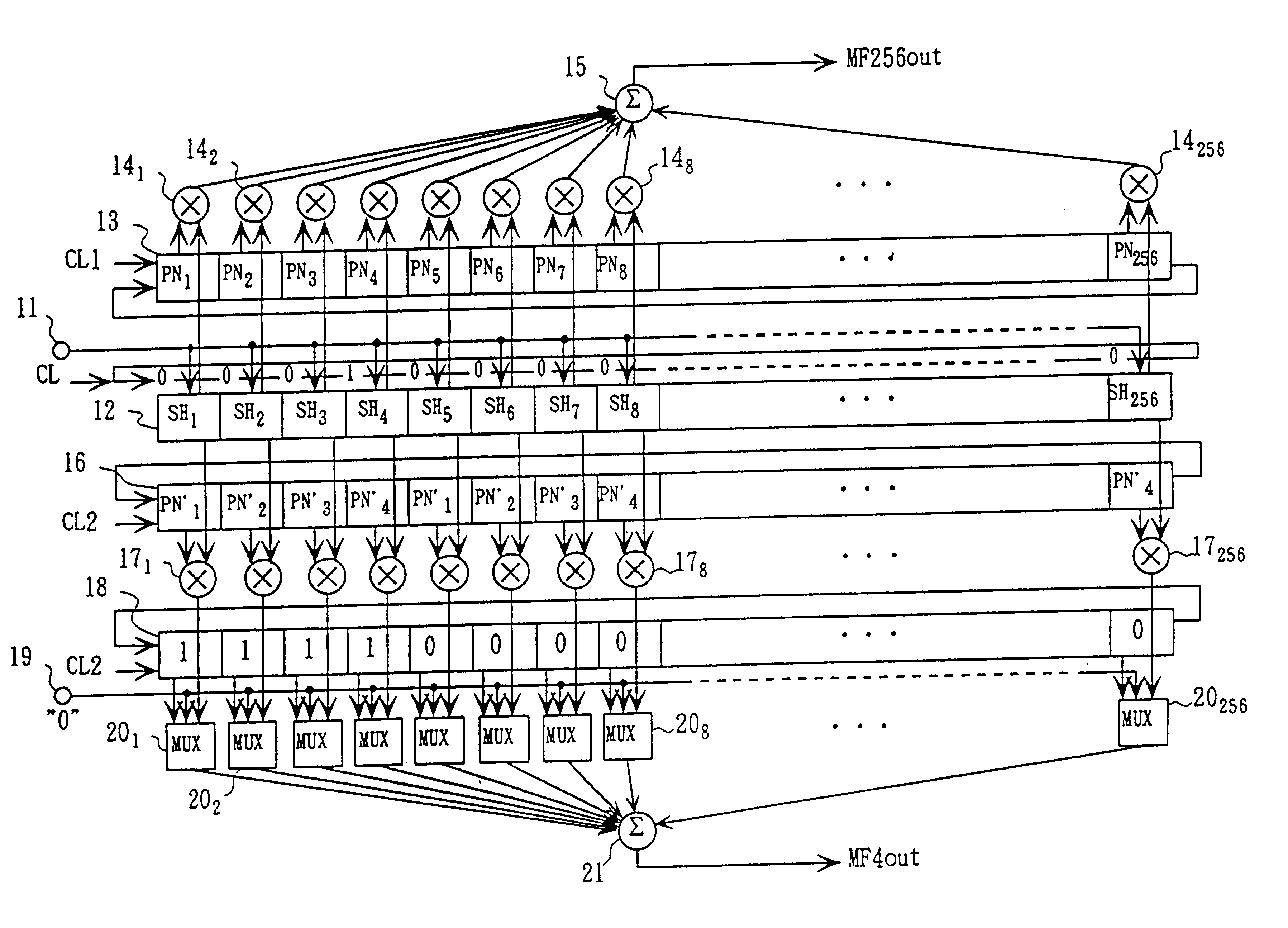
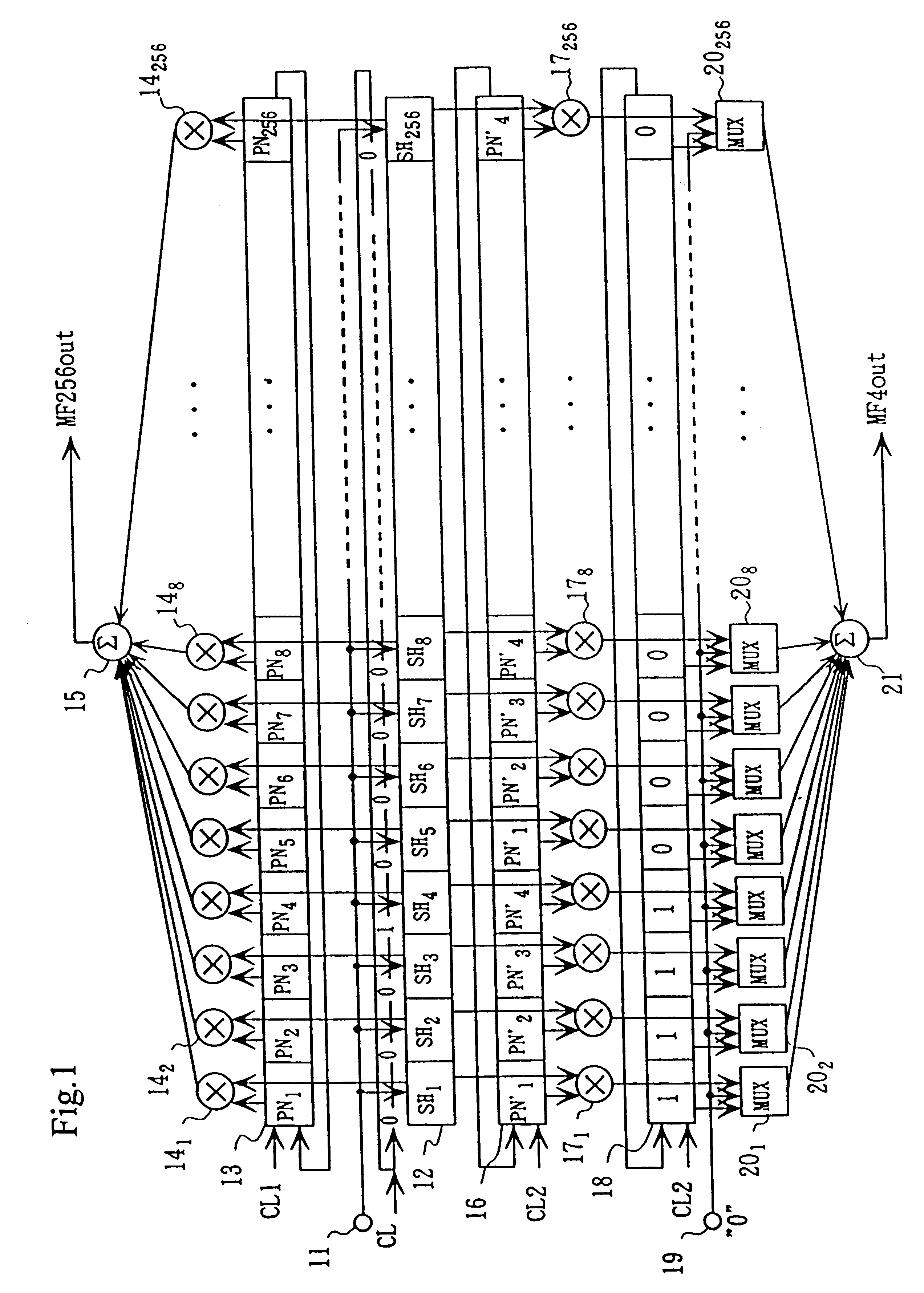
FIG. 1 is a block diagram showing a matched filter bank according to the present invention. In this matched filter bank, input signal samples are not shifted by a PN code sequence is shifted as well as circulated. The matched filter bank is available for correlation of whatever length of coefficient such as PN code sequence for despreading. The matched filter bank may include whatever number of matched filters. In this embodiment, there are two types of PN code sequences having lengths of 4 chips and 256 chips, respectively and there two types of matched filters corresponding to the respective PN code sequences.
In FIG. 1, 11 is an analog signal input terminal that receives a base band signal generated from a received signal through an antenna. 12 is a sampling and holding unit including a plurality, of sampling and holding circuits SH1 to SH256 which are commonly connected to the analog signal input terminal. The sampling and holding circuits receives the input signal in response to...
second embodiment
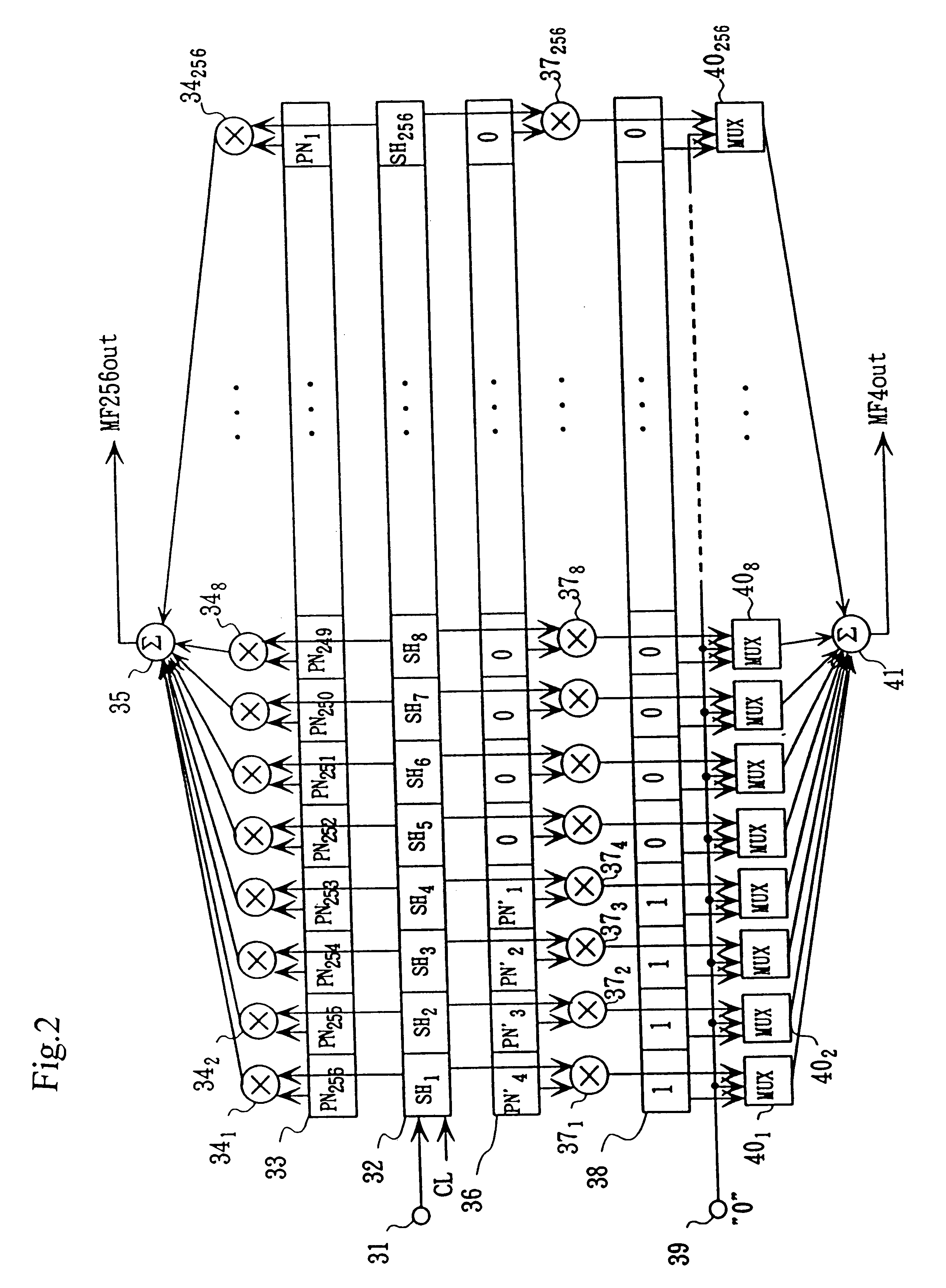
the matched filter bank is described with reference to FIG. 2. The second embodiment is different from the first embodiment only in that the sampling and holding unit 12 is substituted by a sampling shift register 32 which is commonly used for a plurality of PN code sequences. Two PN code sequences of 256 chips and 4 chips are described similar to the first embodiment.
In FIG. 2, 31 is an analog signal input terminal, and 32 is a sampling shift register consisting of a plurality of stages SH1 to SH256. The sampling shift register 32 samples an analog signal input from the input terminal 31 and shifts the sampled data from leading stage to trailing stage. 33 is a first PN code register which stores 256 chips of a first PN code sequence (PN1 to PN256), in this embodiment. 34.sub.1 to 34.sub.256 are multiplication circuits for multiplying outputs from the total stages of the shift register 32 by the PN code (PN1 to PN256) in the PN code register 33. Since the data sampled by and output ...
third embodiment
FIG. 8 shows the matched filter circuit in which one adder 15 is commonly used for processes by a plurality of PN code registers 13 and 16, differently from the circuit in FIG. 1. The outputs from multiplication circuits 14.sub.1 to 14.sub.256 and the outputs from multiplication circuits 17.sub.1 to 17.sub.256 are input to a multiplexer MUX7 which selectively outputs the outputs from the multiplication circuits 14.sub.1 to 14.sub.256 or 17.sub.1 to 17.sub.256 to an adder 15. Therefore, one adder can be commonly used for a plurality of multiplication results and the circuit size becomes small. The more the number of multiplication circuits selected, the smaller the circuit size becomes with respect to the total function. However, the number of selectable multiplication circuits are limited for outputting the total multiplication results within one tip time because the matched filter output must be obtained at the same timing.
An output of the adder 15 is input to a selector SEL7 outpu...
PUM
 Abstract
Description
Claims
Application Information