Optical cable

a flat-type, optical cable technology, applied in the direction of optics, fibre mechanical structures, instruments, etc., can solve the problems of reducing the efficiency of work, requiring revealing work to be tried, damage to optical-fiber cords, etc., to achieve the effect of improving work efficiency

Inactive Publication Date: 2003-01-28
SUMITOMO ELECTRIC IND LTD
View PDF11 Cites 4 Cited by
  • Summary
  • Abstract
  • Description
  • Claims
  • Application Information

AI Technical Summary

Benefits of technology

It is an object of the present invention to provide a flat type optical cable in which it is possible to take optical-fiber cords out at an end portion of a flat type optical cable without any damage of the optical-fiber cords to thereby improve efficiency in the work of treating a terminal of the flat type optical cable.
Even if there is a region in which the cable jacket is partially fusion-bonded to the cord jackets, the cord jackets of the optical-fiber cords are prevented from being deformed or damaged because the cable jacket in this region expands more greatly than the cord jackets so that the cable jacket is broken and separated from the cord jackets.
Hardness and surface smoothness are substantially different concepts from each other. Generally in the case of a plastic material, the extrusion-molded surface becomes denser and smoother in terms of surface roughness as the hardness becomes higher. Accordingly, when a plastic material high in hardness is selected as the coating material for the cord jackets, the surfaces of the cord jackets are smoothed. Hence, even if there is an unevenness in the surfaces of the cord jackets when the cable jacket is formed on the cord jackets by extrusion coating, each recess in the unevenness is so small that a molten resin hardly enters the recess. As a result, the cable jacket is hardly bonded to the cord jackets, so that the cable jacket is easily separated from the cord jackets when revealing is performed.

Problems solved by technology

In the background art, however, as shown in FIG. 3, when the flat type optical cable is subjected to revealing, there is a possibility that the optical-fiber cords may be damaged because the outer coating (hereinafter referred to as cord jacket) of each of the optical-fiber cords as well as the cable jacket are torn out.
If there is such a damage, the revealing work is required to be tried again.
As a result, the efficiency of the work is lowered, so that the laying cost increases as well as the laying term is elongated.

Method used


Image

  • Optical cable
  • Optical cable
  • Optical cable

Examples


examples

(Production of Flat Type Optical Cable)

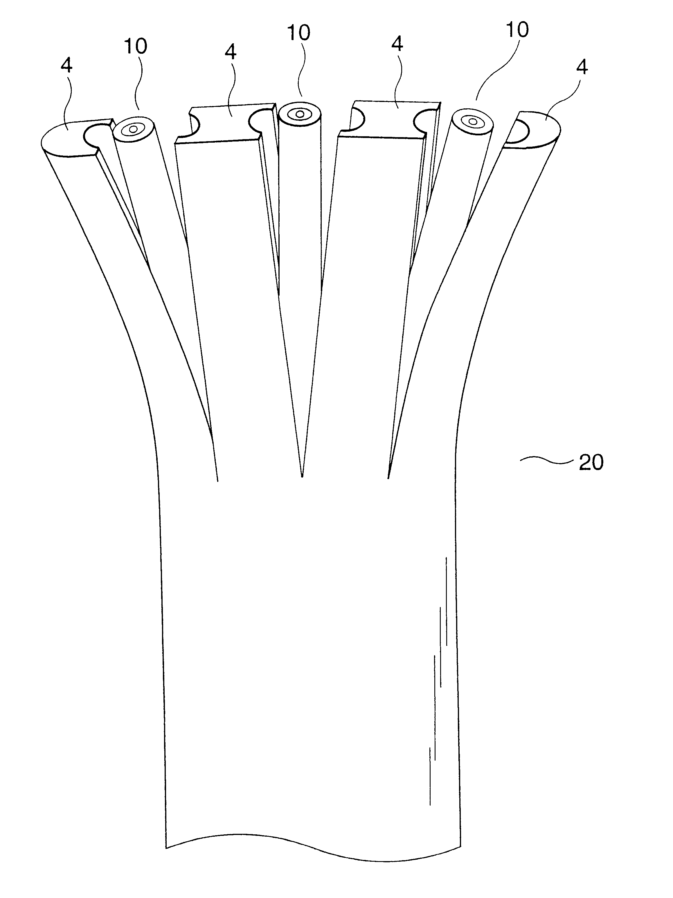
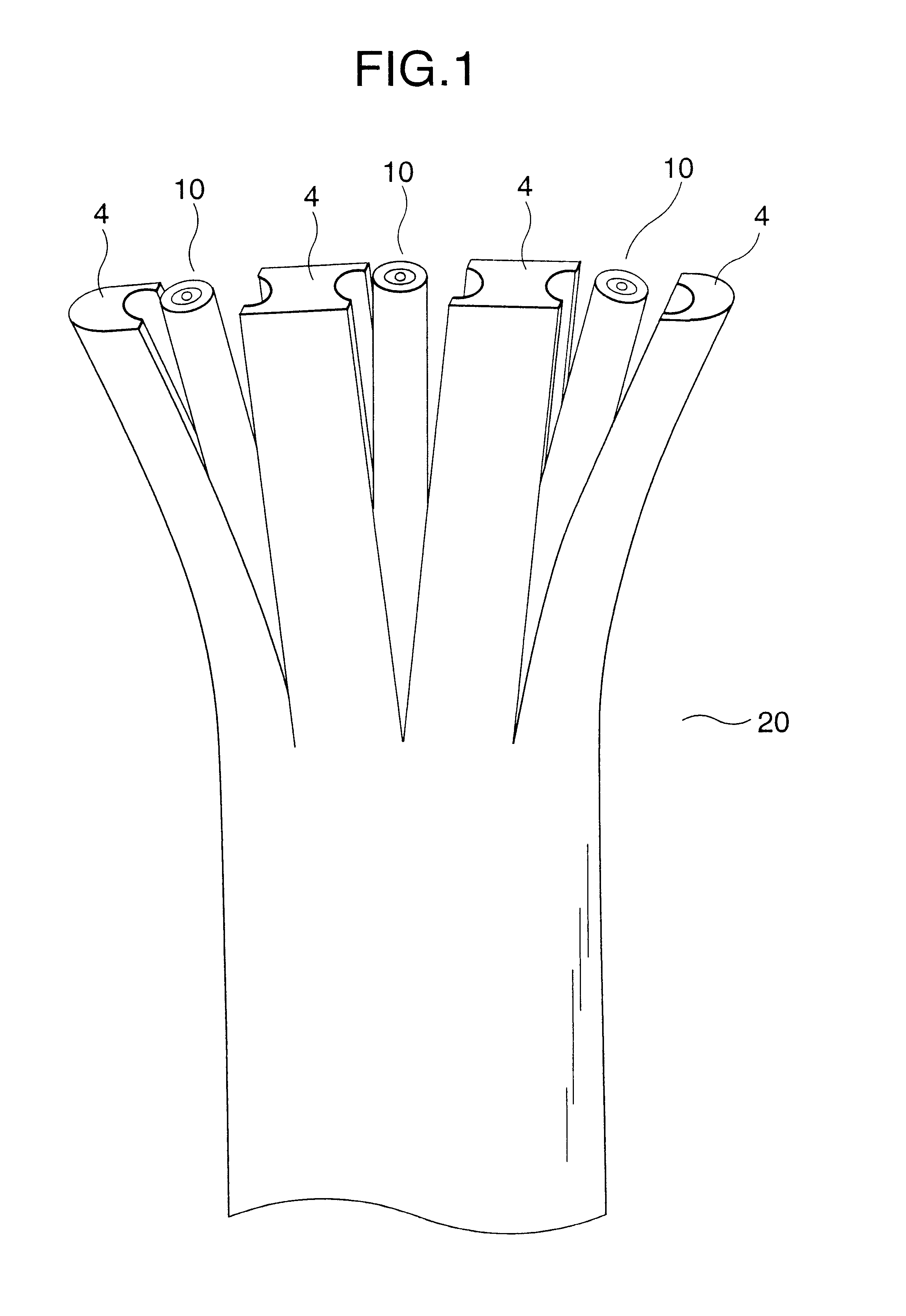
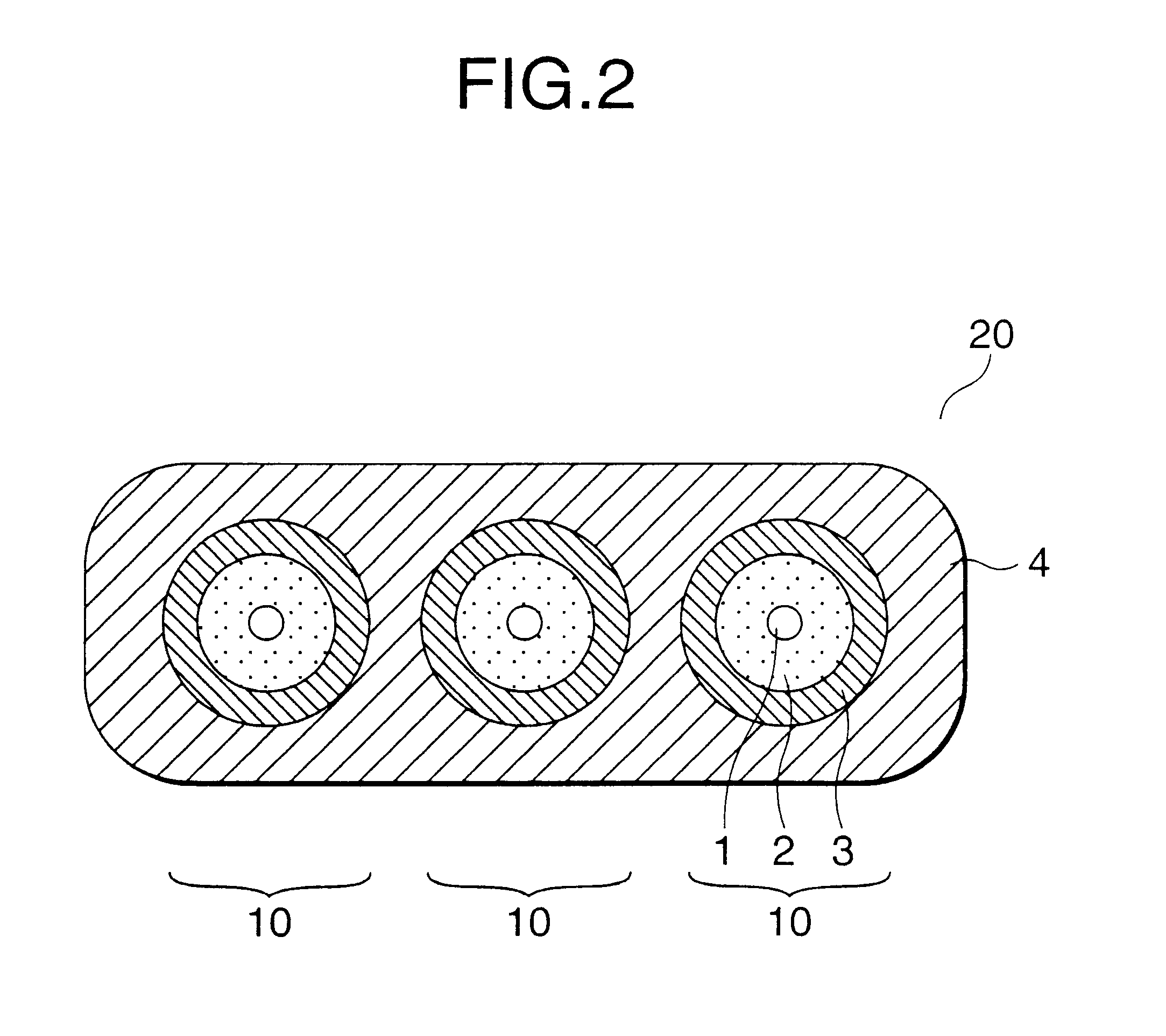
The flat type optical cable as a subject of the embodiments of the present invention has a cross-sectional structure shown in FIG. 2 and is produced in such a manner that three optical-fiber cords 10 each having an outer diameter of 1.5 mm are arranged parallel on a plane and coated with low-density polyethylene to have a size of 7.8 mm wide and 2.6 mm thick.

Each of the optical-fiber cords 10 is produced in a manner such that a fibrous layer 2 of Kevlar is attached longitudinally onto an optical-fiber core 1 and low-density polyethylene is further applied onto the fibrous layer 2 to be an outer diameter of 1.5 mm.

(Revealing Test for Flat Type Optical Cable)

Flat type optical cables 20 each having the aforementioned size are produced by variously changing the combination of the two kinds of low-density polyethylene different both in Young's modulus and in extrusion coating temperature as the plastic materials for forming the cord jackets 3 and th...

example 2

shows the case where a flat type optical cable 20 was produced on the same condition as that in Example 1 except that low-density polyethylene with a Young's modulus of 15 kg / mm.sup.2 as a larger value than 9 kg / mm.sup.2 in Example 1 and an extrusion coating temperature of 200.degree. C. as a higher value than 190.degree. C. in Example 1 was selected for the cord jackets 3 whereas low-density polyethylene with a Young's modulus of 9 kg / mm.sup.2 as a larger value than 4 kg / mm.sup.2 in Example 1 and an extrusion coating temperature of 180.degree. C. as a higher value than 170.degree. C. in Example 1 was selected for the cable jacket 4.

Similarly to Example 1, the optical-fiber cords 10 could be revealed easily without any damage in all cases of five trials.

example 3

shows the case where a flat type optical cable 20 was produced on the same condition as that in Example 1 except that low-density polyethylene with a Young's modulus of 12 kg / mm.sup.2 as a larger value than 9 kg / mm.sup.2 in Example 1 and an extrusion coating temperature of 200.degree. C. as a higher value than 190.degree. C. in Example 1 was selected for the cord jackets 3 whereas low-density polyethylene with a Young's modulus of 9 kg / mm.sup.2 as a larger value than 4 kg / mm.sup.2 in Example 1 and an extrusion coating temperature of 190.degree. C. as a higher value than 170.degree. C. in Example 1 was selected for the cable jacket 4.

Similarly to Example 1, the optical-fiber cords 10 could be revealed easily without any damage in all cases of five trials.


PUM


Abstract

A flat type optical cable is composed of a plurality of optical fiber cords, each including an optical fiber coated with a cord jacket, which are parallel arranged; and a cable jacket which directly coats the cord jackets so that the optical fiber cords are integrated into one optical cable. In the flat type optical cable, the Young's modulus of a coating material forming the cable jacket is lower than the Young's modulus of a coating material forming the cord jacket. Particularly preferably, the Young's modulus of the coating material for forming the cord jacket is in a range of from 9 kg / mm2 to 15 kg / mm2 whereas the Young's modulus of the coating material for forming the cable jacket is in a range of from 4 kg / mm2 to 9 kg / mm2.

Description

1. Field of the InventionThe present invention relates to a flat type optical cable which is integrated by coating a plastic coating layer on parallel arranged optical-fiber cords, particularly relates to a flat type optical cable which is easily subjected to terminal treatment.2. Description of the Related ArtA flat type optical cable having such a cross-sectional structure as shown in FIG. 2 is heretofore mainly used for indoor wiring. The revealing work for taking optical-fiber cords out of the optical cable by removing a part of an outer coating (hereinafter referred to as cable jacket) at an end portion of the optical cable is required when a connector for connecting the optical cable to an apparatus is to be attached to a terminal of the optical cable or when the optical cable is to be connected to another optical cable.Specifically in this revealing work, first, the flat type optical cable is cut longitudinally by about 10 mm by means of a nipper from above the cable jacket a...

Claims


Application Information

Patent Timeline
Patent Type & Authority Patents(United States)
IPC IPC(8): G02B6/44
CPCG02B6/4495G02B6/4403G02B6/4431
Inventor IMAYAMA, TAKAFUMIYAMAMO, MASAYOSHI
Owner SUMITOMO ELECTRIC IND LTD
Why Eureka
Try Eureka