Non-intrusive pressure measurement device for subsea well casing annuli

a pressure measurement device and subsea well technology, applied in the field of wells, can solve the problems of unproven strain gauge method beyond the laboratory stage, difficult detection of body penetration connection, and higher overall safety of wells

Inactive Publication Date: 2003-02-04
FMC TECH INC
View PDF10 Cites 54 Cited by
  • Summary
  • Abstract
  • Description
  • Claims
  • Application Information

AI Technical Summary

Benefits of technology

The annuli between subsea well casings need to be monitored for pressure to ensure the well is being operated in a safe manner and to satisfy regulatory requirements. Traditionally, only the annulus between the production tubing and production casing string is monitored for pressure for wells drilled through marine wellheads. New regulatory requirements may dictate that all casing annuli be monitored for pressure in the future. The present invention enables pressure to be monitored in the outer annuli of the well casing program without adding any pressure containing penetrations to the well system. This non-intrusive approach to monitoring pressure in the annuli preserves the pressure integrity of the well and maximizes the safety of the well.

Problems solved by technology

SCP occurs when one or more leaks develop in the barriers designed to achieve and maintain pressure control of wells.
Even if penetrations were allowed in subsea wellhead, housings, the overall safety of the well would be at higher-risk because each wellhead penetration creates a potential leak point.
Obviously when a wellhead is located at or near the seabed leakage or a body penetration connection would be difficult to detect until a major problem has occurred.
The strain gauge method has not progressed beyond the laboratory stage due to technical concerns about implementing the method for the subsea environment.
The seals and ports on the adjustable sleeve are potential leak points that increase the overall safety risk for the well.
Orientation of the couplers prior to tree / wellhead makeup is critical and the couplers are subject to damage.
Each port is a potential leak point that increases the overall safety risk for the well.
This requirement may present a safety risk to subsea wells, because the most straightforward method of accessing an annulus for pressure monitoring is to make a pressure containing penetration through the body of the pressure vessel.
Since it is well known that all penetrations through the outer pressure containing housing of wellheads are potential leak points which add sealing risk, and thus safety risk, to the well system pressure monitoring in all well annuli will not be practical unless a safe system for doing so becomes commercially available.
A further complication is that API Specification 17D for Subsea Wellhead and Christmas Tree Equipment explicitly prohibits body penetrations in high pressure subsea wellhead housings.
Otherwise, well safety may be compromised rather than improved.
If SCP results from formation pressure, the most likely causes are cement or structural failures.
Therefore, the need to monitor SCP in all casing annuli is questionable and should only be considered if a highly reliable means of achieving it can be established.
The reliability of any new SCP monitoring system should be equal to or better than current practice, otherwise, well safety may be compromised.
Every penetration is a potential leak point that decreases reliability.
All intrusive methods add leak points, either externally through the wellhead housing or internally through movable seals on the casing hangers.
Even though non-intrusive methods do not add leak points, their reliability at this point in time is unknown because non-intrusive methods are not fully developed and field proven.
The cost associated with implementing a / multi-annulus pressure -monitoring system will depend on the method employed.
Since the recommended method is a non-intrusive approach, and functional, field proven, non-intrusive methods do not exist at this time, the cost of implementation cannot be accurately estimated.
However, the cost will be significant because wellhead systems, control systems and production umbilicals will all be impacted.
The additional cost may preclude developing wells that are already considered economically marginal.

Method used


Image

  • Non-intrusive pressure measurement device for subsea well casing annuli
  • Non-intrusive pressure measurement device for subsea well casing annuli
  • Non-intrusive pressure measurement device for subsea well casing annuli

Examples


Embodiment Construction

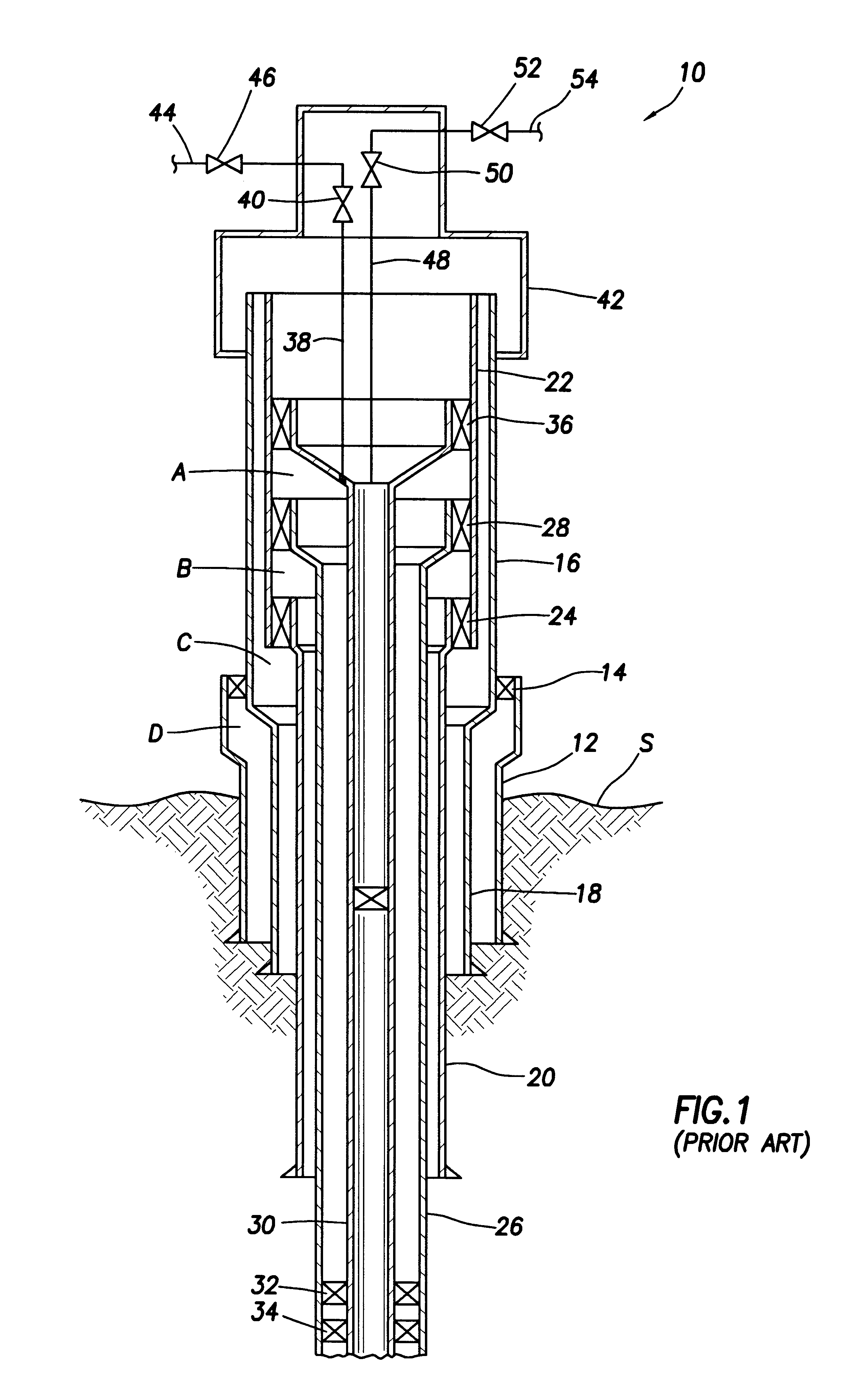
FIG. 1 of the Drawings schematically illustrate a wellhead having multiple annuli and showing a conventional system representing the prior art for detecting pressure conditions within the production tubing outlet at the tubing hangar and detecting pressure conditions within annulus "A". The pressure measurement system of FIG. 1 is of non-intrusive nature but it does not have the capability for measuring the pressure of other annuli.

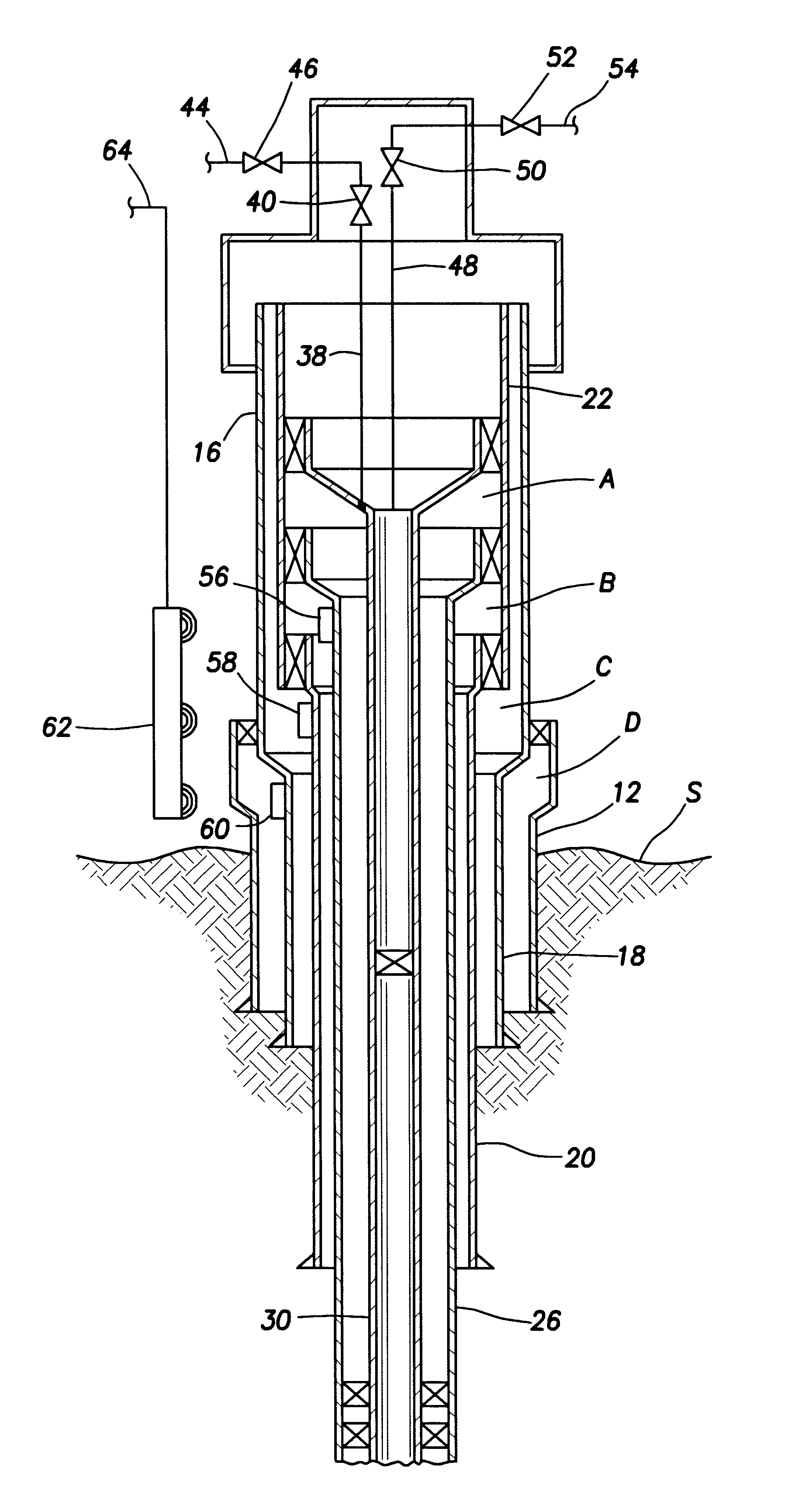
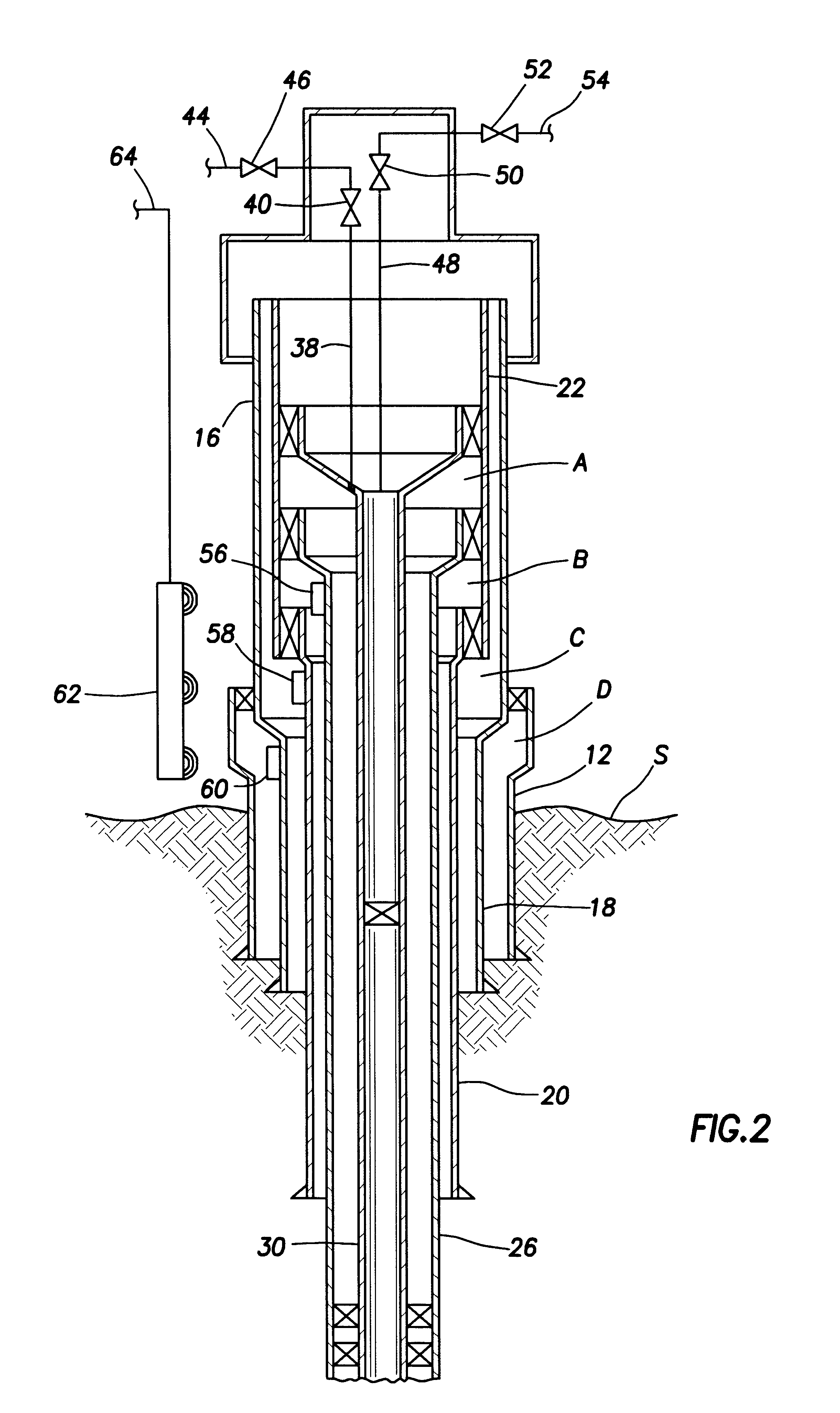
FIG. 2 of the Drawings illustrates a non-intrusive pressure monitoring system for well casing annuli, representing the preferred embodiment of the present invention that consists of intelligent pressure sensors mounted on the casing hangers and / or casing strings and a means to remotely interrogate those sensors. The interrogation device may be located external to the wellhead or may be located internal to the wellhead on or within the completion tubing hanger or tubing string. The invention does not require any penetrations through the high or low pressur...


PUM


Abstract

A well data monitoring system which enables annulus pressure and other well parameters to be monitored in the outer annuli of the well casing program without adding any pressure containing penetrations to the well system. This non-intrusive approach to monitoring pressure and other well parameters in the annuli preserves the pressure integrity of the well and maximizes the safety of the well. In the preferred embodiment an intelligent sensor interrogation system which can be located externally or internally of the pressure containing housing of the wellhead is capable of interrogating and receiving data signals from intelligent well data sensors which are exposed to well parameters within the various annuli of the well and wellhead program.

Description

1. Field of the InventionThe present invention pertains generally to wells for production of petroleum products and more specifically concerns wells located in a subsea environment where the pressure containing integrity of wells is of particular concern from the standpoint of environmental protection and for protection of workers and equipment from the hazards of pressure leakage from wells. More particularly, the present invention provides a non-intrusive method for monitoring pressure in well casing annuli without compromising the pressure containing integrity of the well system in any way, and thus permitting excessive pressure in typically inaccessible annuli to be detected, and corrective actions taken before a hazardous event can occur that might impact human life, the environment or property.2. Description of the Prior ArtWhile the present invention has application to petroleum producing wells other than subsea well systems, for purposes of simplicity and to facilitate ready...

Claims


Application Information

Patent Timeline
Patent Type & Authority Patents(United States)
IPC IPC(8): E21B47/06E21B47/00
CPCE21B47/06E21B47/0001E21B47/001
Inventor WESTER, RANDY J.
Owner FMC TECH INC
Why Eureka
Try Eureka