System for vehicle emission sampling and measurement

a technology for vehicle emission sampling and measurement, applied in the direction of engine testing, structural/machine measurement, instruments, etc., can solve the problems of inability to sample the ambient air encountered in actual driving conditions, inability to significantly alter test data, and inability to sample the moisture in the line significantly, so as to increase the efficiency of drying tubes

Inactive Publication Date: 2003-02-11
HONDA MOTOR CO LTD
View PDF21 Cites 32 Cited by
  • Summary
  • Abstract
  • Description
  • Claims
  • Application Information

AI Technical Summary

Benefits of technology

Additionally, the vehicle emission sampling and measurement system may further comprise a water removal system for drying the gas streams prior to analysis in the analyzers. This water removal system may comprise a plurality of drying tubes coupled together in series, the drying tubes having a first flow path for the gas being sampled and a second flow path for a purge gas. Furthermore, the water removal system may comprise a series of heating and cooling stages wherein the efficiency of the drying tubes is increased. The analyzers may comprise Fourier transformer infrared spectrometer devices wherein the constituent chemical components of the gases are analyzed on a continuous real-time basis. In such a system, both the vehicle emissions and the ambient air are continuously gathered, analyzed and compared, and the results are stored and displayed in a real-time format.
A more complete understanding of the emissions sampling and measurement system will be afforded to those skilled in the art, as well as a realization of additional advantages and objects thereof, by a consideration of the following detailed

Problems solved by technology

Automobile exhaust is a major air pollutant, contributing to increased health concerns and also such unappealing environmental conditions as smog.
However, this process does not sample the ambient air encountered in actual driving conditions for comparison with the vehicle exhaust.
One of the chief problems faced in sampling exhaust from near-zero emission vehicles is obtaining a dry sample.
Any moisture in the line can significantly alter test data.
All three of these methods have drawbacks.
Furthermore, even when maintained in a vapor state, the moisture may provide interference with certain low level FTIR measurement analysis.
Diluting the gas with large quantities of a non-reactive gas decreases the level of sensitivity of the sample that can be obtained due to the dilution of the sample contents, thus providing a less accurate analysis.
Also, dilution requires the presence of large tanks containing the diluting gas, making a compact system difficult to achieve.
Alternatively, if ambient air is used in the dilution process, the pollutants in the ambient air may have an adverse effect on pollutant measurements when dealing with near-zero emission vehicles.
While it is known to remove moisture from gases utilizing selectively permeable materials in fields such as medicine and in exhaust gases, no system exists that is both compact and efficient enough to provide the level of water removal required to allow for accurate testing onboard a moving near-zero emission vehicle.
Presently, no device exists for real-time comparison of the level of pollutants in the vehicle exhaust to those found in the ambient atmosphere while the vehicle is travelling.
For instance, in those urban environments where the level of ambient pollutants in the atmosphere is high, such high levels may distort the measurements being recorded concerning the vehicle exhaust.
Although conventional systems may detect pollutant levels, there remains an unmet need for a system that is compact enough to be placed on-board an automobile and that is able to measure the pollutant levels in a vehicle exhaust and compare those levels to the ambient atmosphere.

Method used


Image

  • System for vehicle emission sampling and measurement
  • System for vehicle emission sampling and measurement
  • System for vehicle emission sampling and measurement

Examples


Embodiment Construction

The present invention satisfies the need for a compact and efficient process for analyzing exhaust from a low level emissions motor vehicle and comparing the pollutants found in the exhaust with those found in the atmosphere. In the detailed description that follows, like element numerals are used to describe like elements illustrated in one or more of the figures.

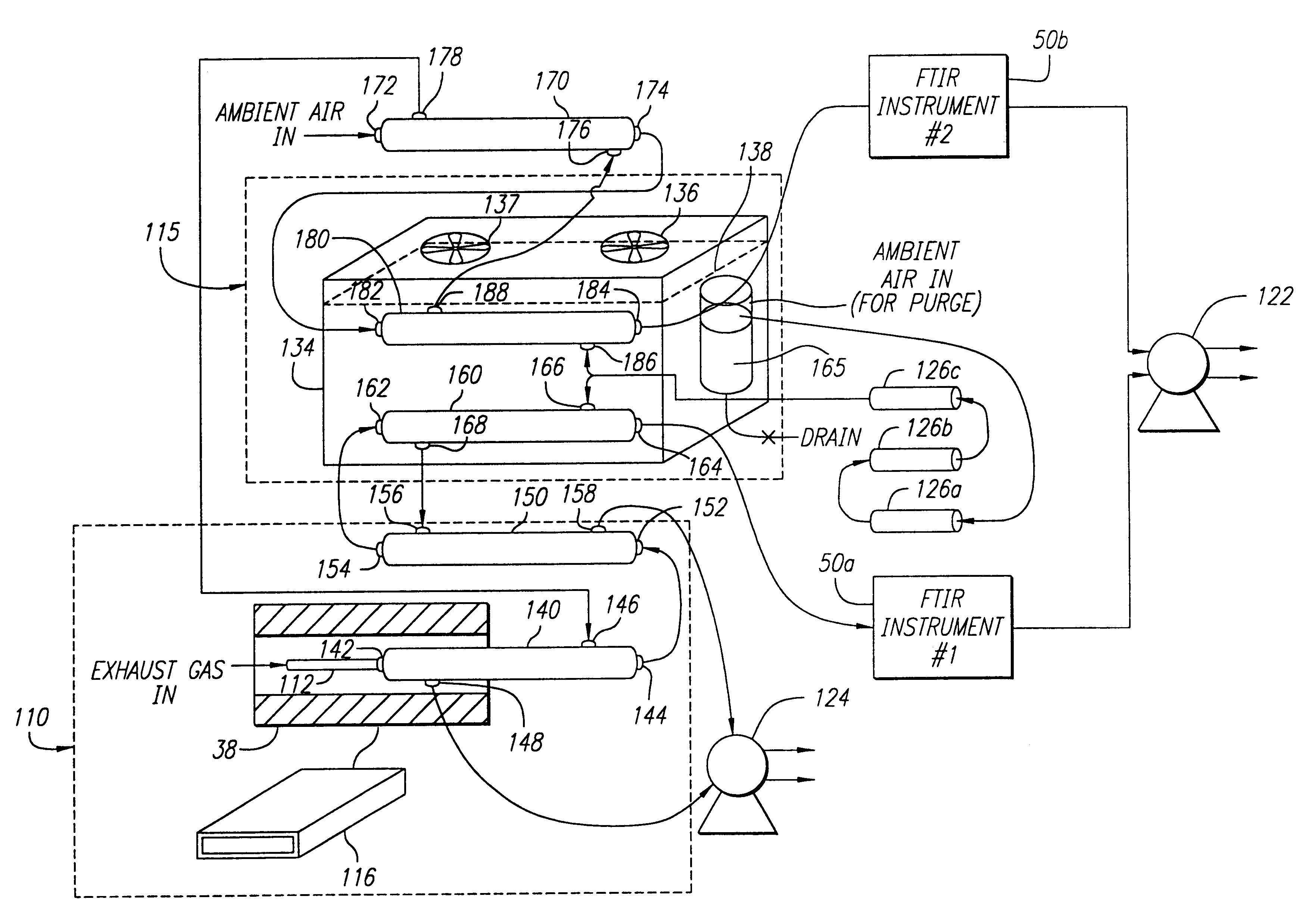
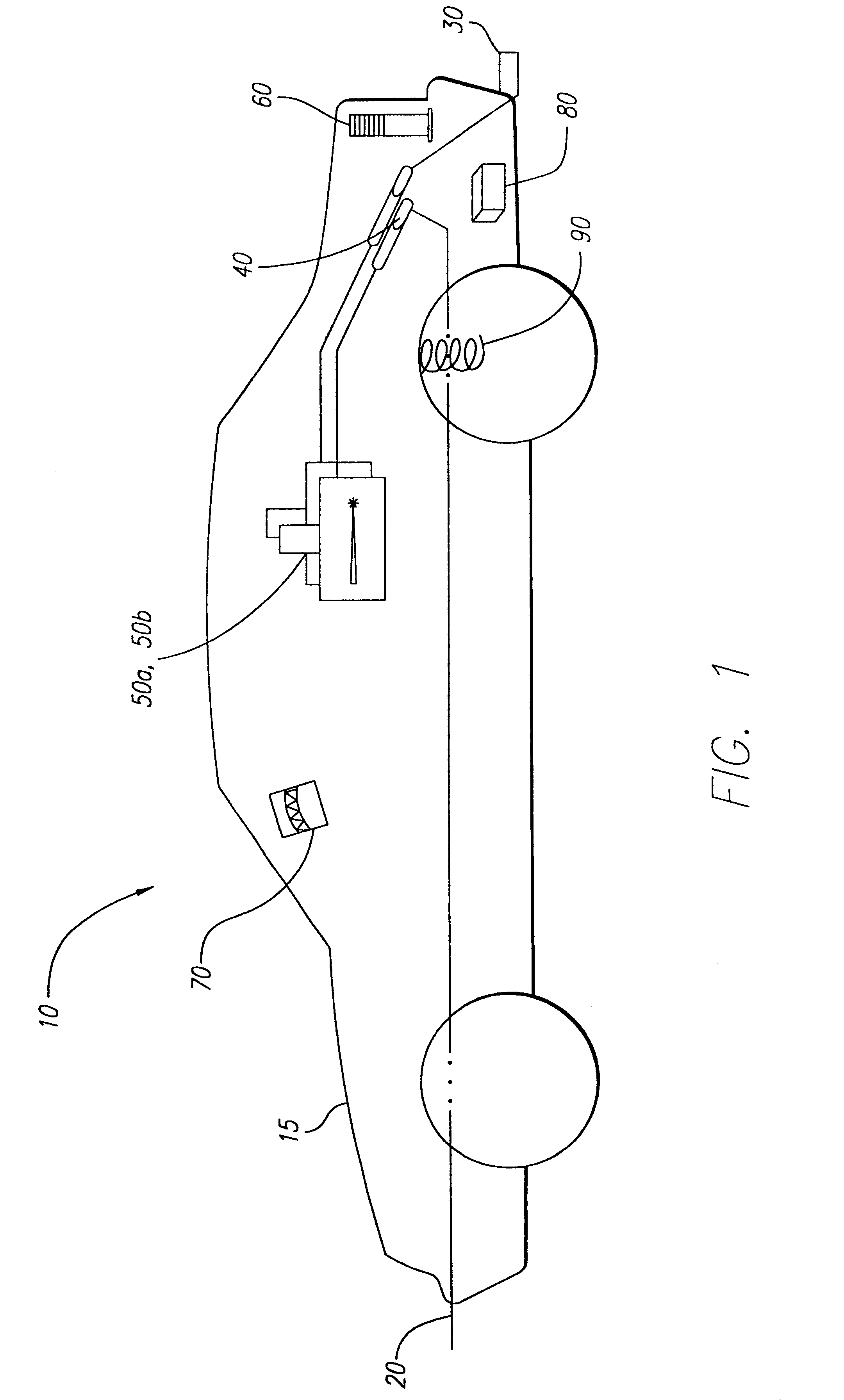
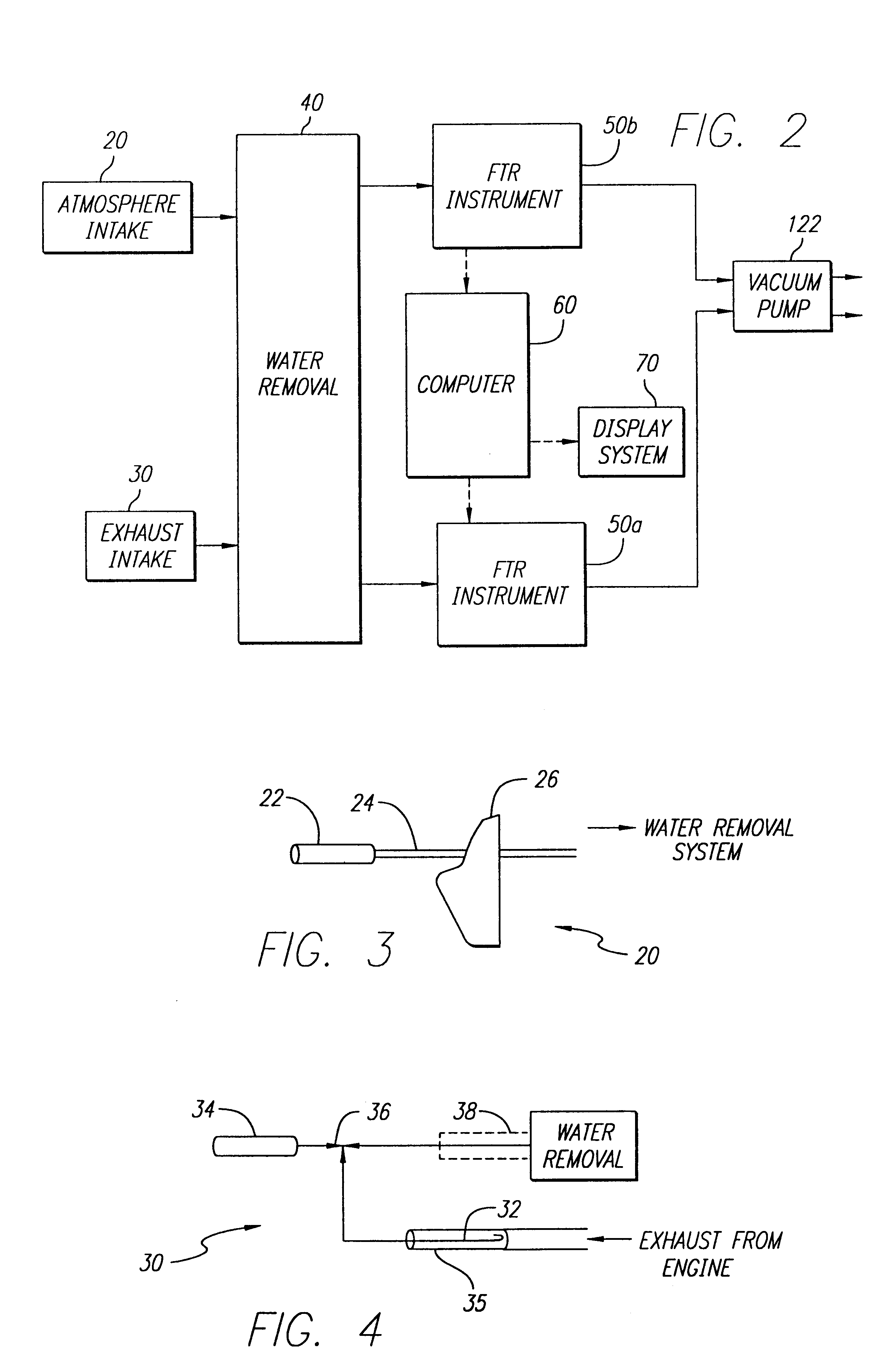
Referring first to FIG. 1 of the drawings, a system schematic drawing of an emissions measuring system 10 is shown. The emissions measuring system 10 comprises an outside air intake 20, an exhaust intake 30, a water removal system 40, Fourier transformer infrared instruments 50a, 50b, and a computer 60. The emissions measuring system is incorporated within a motor vehicle 15 having an emission source, such as an internal combustion motor (not shown). For purposes of this description, a sedan type model vehicle 15 has been depicted; however, it should be readily apparent to one skilled in the art that the emissions measurin...


PUM


Abstract

An improved emission sampling and measurement system is provided for continuously sampling and analyzing the chemical content of a vehicle emissions and the ambient air for data evaluation and comparison. The emission sampling and measurement system comprises a vehicle having an emissions source, devices for intaking vehicle emissions and ambient air, and analysis devices for determining the chemical content of the emissions and ambient air. The gas streams may be dried in a series of selectively permeable drying tubes prior to measurement in the analysis devices, in order to effectuate a more precise sample of the constituent elements of the gases. Following analysis, the data collected is processed, stored, and compared, and the results displayed on a screen in the vehicle driver's compartment in a real-time manner. In this fashion, real-time comparative data analysis is presented in a format not presently available.

Description

BACKGROUND OF THE INVENTION1. Field of the InventionThe present invention relates to an apparatus for making real time evaluations of pollutants in the exhaust gas emissions of motor vehicles, and is particularly, but not exclusively, applicable to the measurement of emissions from near-zero level emissions vehicles. It further relates to the comparison of the levels of contaminants in the exhaust gas emissions of vehicles to the level of pollutants in the ambient air through which the vehicle is travelling.2. Description of Related ArtAutomobile exhaust is a major air pollutant, contributing to increased health concerns and also such unappealing environmental conditions as smog. Los Angeles, well known for its brown haze, is of late only one of a number of major cities to deal with the problem of pollutants. In the fight to combat the deleterious effects of automobile exhaust pollutants, the federal government and many states have required emissions testing of automobiles. A more r...

Claims


Application Information

Patent Timeline
Patent Type & Authority Patents(United States)
IPC IPC(8): G01M19/00G01M15/10G01M99/00
CPCG01M15/102
Inventor JETTER, JEFFREY JAYMAESHIRO, SHINJIYAMAZAKI, KAZUMI
Owner HONDA MOTOR CO LTD
Why Eureka
Try Eureka