All optical logic using cross-phase modulation amplifiers and mach-zehnder interferometers with phase-shift devices

a phase-shift device and amplifier technology, applied in the field of all optical logic, can solve the problems of difficult production, high cost, and high cost of optical logic elements, and achieve the effects of reducing the cost of production

Inactive Publication Date: 2003-02-18
SUPER TALENT ELECTRONICS
View PDF21 Cites 57 Cited by
  • Summary
  • Abstract
  • Description
  • Claims
  • Application Information

AI Technical Summary

Problems solved by technology

Since photons travel faster than electrons, much effort has gone into trying to develop an optical computer or optical logic elements.
Most of these approaches have proven to be difficult to produce, expensive, or bulky.
Finally, constructive or destructive interference occurs where the two interferometer arms are combined to generate the final output C.
While useful, the counter-propagation of the logical inputs can feed back to the continuous-wave input, which may cause cross-talk among other gates that share the same continuous-wave signal source.
Splitting of the continuous-wave signal power may not be the ideal 50%-50% due to geometry or orientation imperfections of the Y-junctions.
Constructive and destructive interference of the two inputs occurs within the waveguide.
The signal components at each output can interfere with each other constructively or destructively.
The additional power changes the refractive index of the SOA and thus causes the phase shift.
Another disadvantage is a power management issue.
But the disadvantage is that the input A could disturb the input B.
This can be a challenging design goal, especially for more complex logic gates.
The disadvantage of this structure is the logic input could disturb the input CW.
However, the problem may be more serious for integrated optics that have the CW laser source built into a single chip.
The phase difference of .pi. causes destructive interference at the upper Y-junction, resulting in a dark signal being applied to the upper input of MMI combiner 84.
The phase difference of .pi. causes destructive interference at the lower Y junction.
Destructive interference occurs for the lower Y-junction, but constructive interference for the upper Y junction.

Method used


Image

  • All optical logic using cross-phase modulation amplifiers and mach-zehnder interferometers with phase-shift devices
  • All optical logic using cross-phase modulation amplifiers and mach-zehnder interferometers with phase-shift devices
  • All optical logic using cross-phase modulation amplifiers and mach-zehnder interferometers with phase-shift devices

Examples


Embodiment Construction

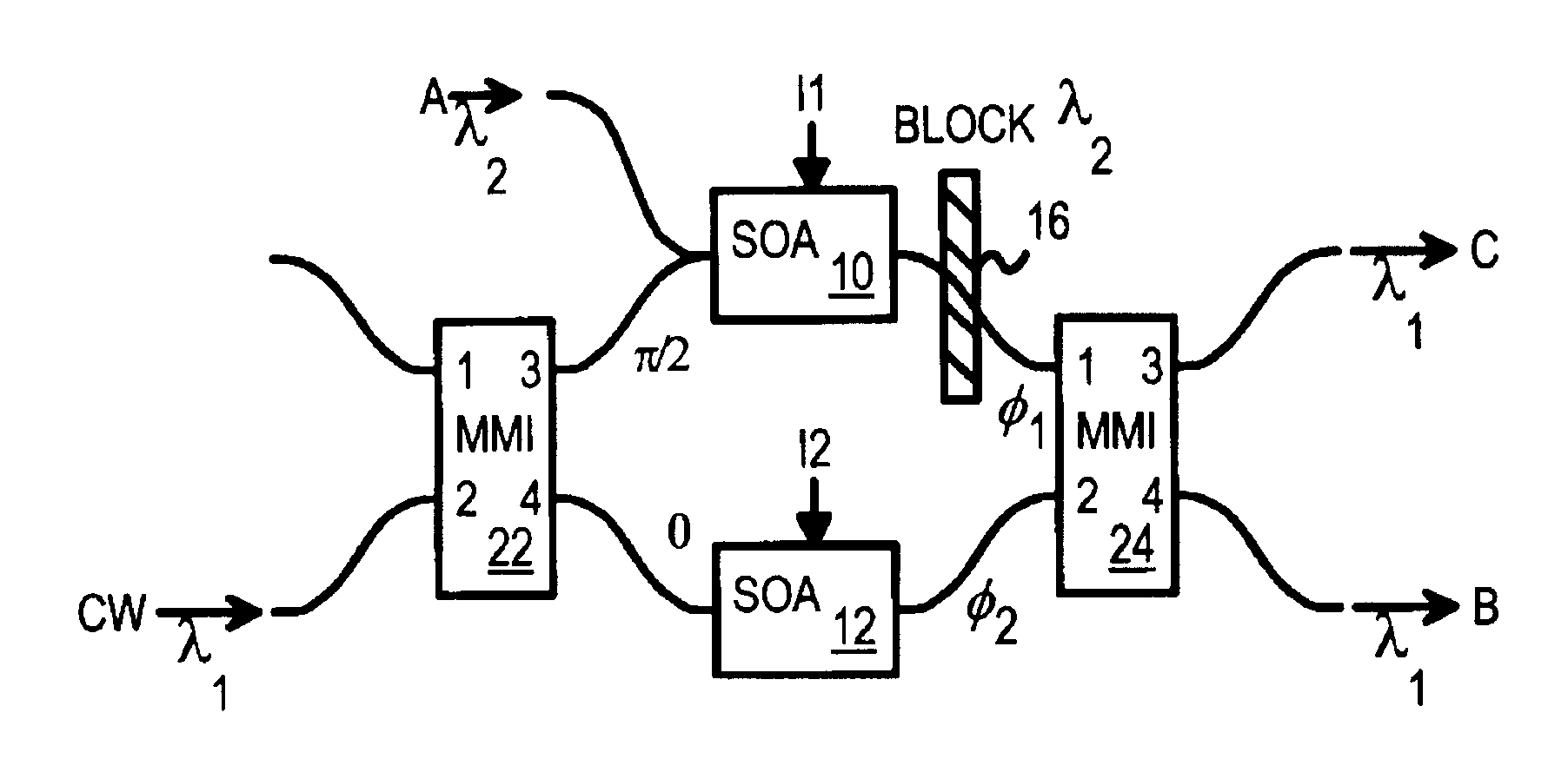
Several other embodiments are contemplated by the inventors. For example, larger MMI devices could be used, and logic gates with more inputs produced. Even larger, more complex logic functions with multiple inputs are contemplated, such as AND-OR networks.

Semiconductor optical amplifiers (SOA's) can be constructed from a variety of materials. Rather than use an electrical bias current to the SOA's, an optical pump bias could be used, or some other energy-adding method. The SOA's or phase shifters could also operate with a phase shift that is normally .pi., or some other value, rather than normally 0, in the absence of optical power from the logic input signal. The bias could be fixed into the SOA's or the branches. The relative phase shifts of the two SOA's could also be set to differ in the absence of optical power from logic input signal. The MMI's could vary in design and have diagonal phase shifts other than .pi. / 2.

While the phase differences among the two SOA's has been describ...


PUM

PropertyMeasurementUnit
phaseaaaaaaaaaa
opticalaaaaaaaaaa
wavelengthaaaaaaaaaa

Abstract

Optical logic gates are constructed from Mach-Zehnder Interferometer (MZI) optical circuits. A multi-mode interference (MMI) splitter divides a continuous-wave input into two branches of the interferometer. Each branch has a semiconductor optical amplifier (SOA). When a logic input having a logic-high power level is applied to one of the SOA's, cross-phase modulation occurs in the SOA. The phase shift increases through the SOA. The branch coupled to the logic input has a relative phase shift of pi compared with the other branch. When two branches with the pi phase difference are combined, destructive interference occurs, producing a logic low. An MMI combiner or an equivalent phase shifter is used to combine the two branches. The MMI splitter adds a phase shift of pi / 2 to the upper branch but not to the lower branch, while the MMI combiner also adds pi / 2 shifts.

Description

BACKGROUND OF INVENTIONThis invention relates to all-optical logic elements, and more particularly to the use of interferometers with semiconductor optical amplifiers (SOA) and multi-mode interference (MMI) devices.Since photons travel faster than electrons, much effort has gone into trying to develop an optical computer or optical logic elements. Different approaches have been taken to developing optical logic and other elements of a computer. Most of these approaches have proven to be difficult to produce, expensive, or bulky.Optical logic gates are using an interferometer are disclosed by Roberts et al. in U.S. Pat. No. 5,999,283. FIG. 1A is a prior-art interferometer-based exclusive-OR (XOR) gate. A continuous-wave light input is split into two branches to semiconductor optical amplifiers (SOA) 6, 8. Modulated input A is combined with the output of SOA 8, while modulated input B is combined with the output of SOA 6. Outputs of SOA 6, 8 are combined to produce the logic-gate outp...

Claims


Application Information

Patent Timeline
Patent Type & Authority Patents(United States)
IPC IPC(8): G02F2/00G02F3/00H01S5/50H01S5/00
CPCG02F2/004H01S5/50G02F3/00G02F2203/70G02B6/29352G02B6/26
Inventor CHU, TZU-YIHCHANG, SHYANGAU, CHIMA, ABRAHAM C.
Owner SUPER TALENT ELECTRONICS
Why Eureka
Try Eureka