
Metal halide lamp with lithium and cerium iodide

Inactive Publication Date: 2003-02-25
KONINKLIJKE PHILIPS ELECTRONICS NV
View PDF9 Cites 30 Cited by
  • Summary
  • Abstract
  • Description
  • Claims
  • Application Information

AI Technical Summary

Benefits of technology

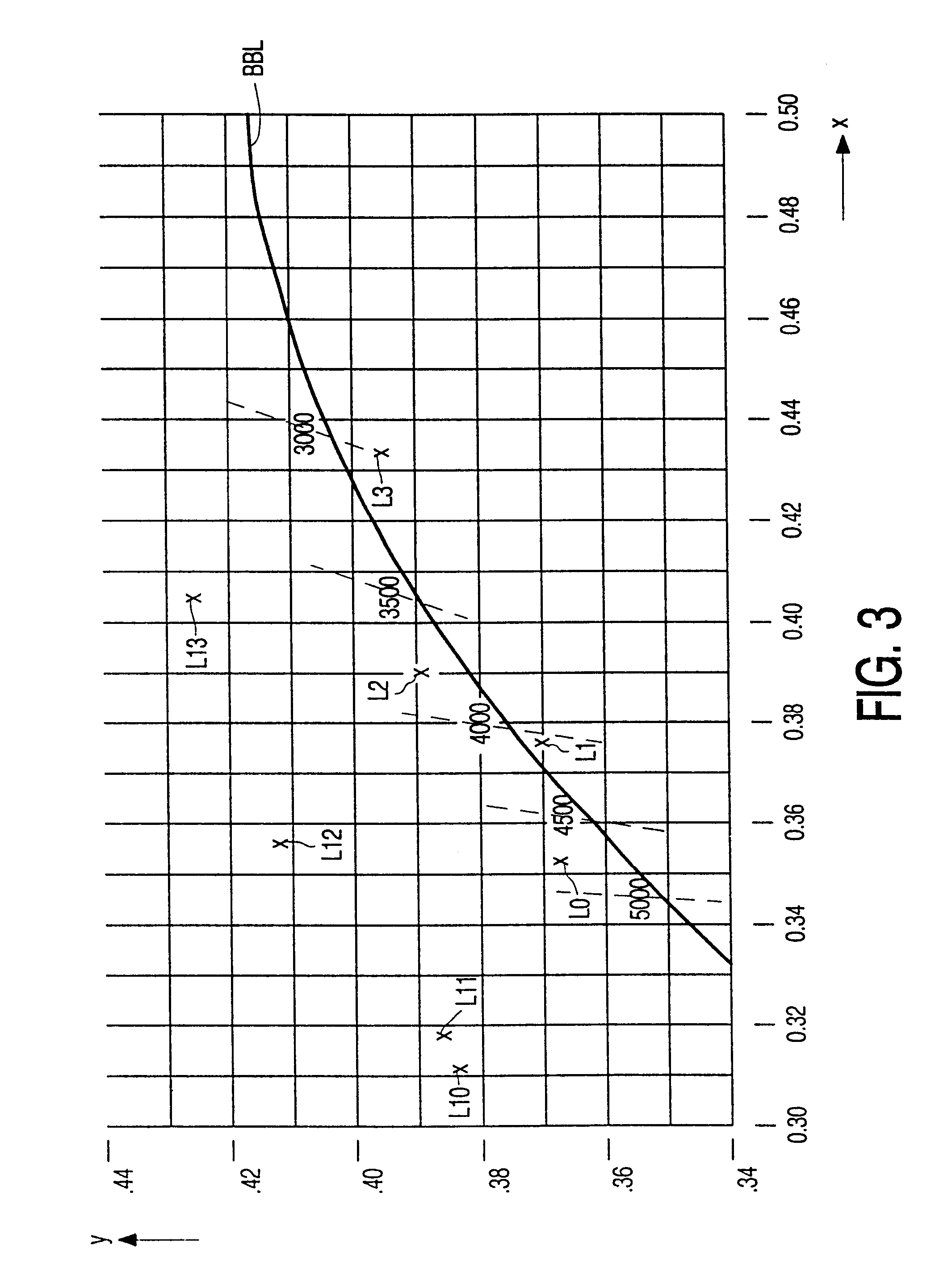
By means of this measure, the lamp emits light with a high luminous efficacy and with a color point which is so close to the BBL that the light emitted by the lamp can be considered to be white light for indoor lighting applications. This is further favorably influenced by the choice of LiI and CeI.sub.3 in a molar ratio ranging between 1 and 8. In an advantageous embodiment of the lamp in accordance with the invention, the alkali halide also comprises NaI. Apart from the preservation of a color point which is so close to the BBL that the lamp can be used for indoor lighting purposes, the presence of NaI enables the color point of the lamp to be chosen in a wide range along the BBL. Preferably, LiI and NaI are jointly present in a molar ratio relative to CeI.sub.3 ranging between 4 and 10. This enables a lamp to be obtained whose emitted light has a color point whose co-ordinates differ less than (0.015; 0.015) from the BBL, while the color temperature of the light ranges between 3000 K and 4700 K.
A further improvement as regards the control of the wall temperature and of thermal stresses in the wall of the discharge vessel can be achieved by a suitable choice of the wall thickness. The good thermal conductivity of the ceramic wall is further advantageously used if the ceramic wall has a thickness of at least 1 mm. An increase of the wall thickness results in an increase of the thermal radiation through the wall of the discharge vessel, but above all it contributes to a better heat transport from the part of the wall between the electrodes to the relatively cool ends of the discharge vessel. In this manner, it is achieved that the temperature difference occurring at the wall of the discharge vessel is limited to approximately 200 K. An increase of the wall thickness also leads to a decrease of the load on the wall.
In general, a noble gas for ignition of the lamp is added to the ionizable filling of the discharge vessel. The choice of the filling pressure of the noble gas enables the light-technical properties of the lamp to be influenced.

Problems solved by technology

It has also been found that, as a result of this geometry, the wall of the discharge vessel is subject to such uniform heating that the risk of fracture of the wall of the discharge vessel as a result of thermal stress is very small.
A drawback of this lamp is that it has a relatively limited luminous efficacy.
However, as a result of its very strong reactive character, Sc proved to be unsuitable for use in a metal-halide lamp having a ceramic lamp vessel.

Method used


Image

  • Metal halide lamp with lithium and cerium iodide
  • Metal halide lamp with lithium and cerium iodide
  • Metal halide lamp with lithium and cerium iodide

Examples


Embodiment Construction

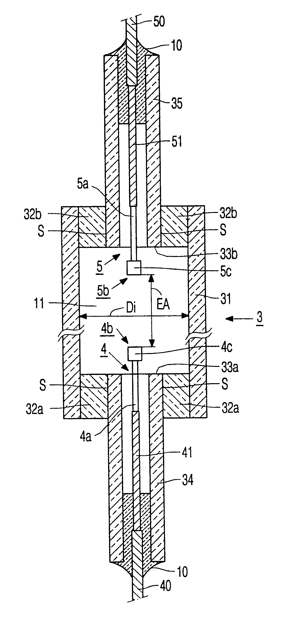
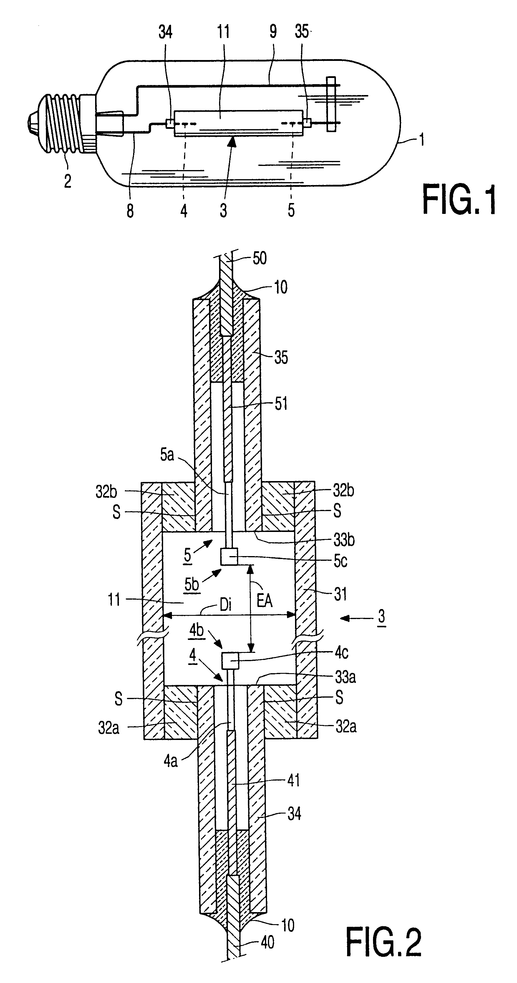
FIG. 1 shows a metal-halide lamp provided with a discharge vessel 3 having a ceramic wall which encloses a discharge space 11 containing an ionizable filling including at least Hg, an alkali halide and CeI.sub.3. Two electrodes whose tips are at a mutual distance EA are arranged in the discharge space, and the discharge vessel has an internal diameter Di at least over the distance EA. The discharge vessel is closed at one side by means of a ceramic projecting plug 34, 35 which encloses a current lead-through conductor (FIG. 2: 40, 41, 50, 51) to an electrode 4, 5 positioned in the discharge vessel with a narrow intervening space and is connected to this conductor in a gastight manner by means of a melting-ceramic joint (FIG. 2: 10) near to an end remote from the discharge space. The discharge vessel is surrounded by an outer bulb 1 which is provided with a lamp cap 2 at one end. A discharge will extend between the electrodes 4, 5 when the lamp is operating. The electrode 4 is connec...


PUM


Abstract

Metal halide lamp includes a discharge vessel having a ceramic wall with an internal diameter Di and enclosing two electrodes whose tips are a distance EA apart, wherein EA / Di>5. The vessel has a filling comprising Hg, CeI, and LiI.

Description

BACKGROUND OF THE INVENTIONThe invention relates to a metal-halide lamp comprising a discharge vessel with a ceramic wall which encloses a discharge space with an ionizable filling including at least Hg, an alkali halide and CeI.sub.3, and which discharge space further accommodates two electrodes whose tips are arranged at a mutual distance EA, and the discharge vessel has an inside diameter Di at least over the distance EA, and the relation EA / Di>5 is met.A lamp of the type mentioned in the opening paragraph is known from the European patent application No. 96203434.4 U.S. Pat. No. 5,993,453. The known lamp, which combines a high luminous efficacy with acceptable to good color properties (inter alia a general color rendering index R.sub.a.gtoreq.45 and a color temperature T.sub.c in the range between 2600 and 4000 K) can particularly suitably be used as a light source for, inter alia, general lighting purposes. As a result of the comparatively small diameter with respect to the ...

Claims


Application Information

Patent Timeline
IPC IPC(8): H01J61/12H01J61/20H01J61/30H01J61/88
CPCH01J61/125H01J61/827H01J61/30H01J61/12
Inventor GEIJTENBEEK, JOHANNES J. F.VERMEULEN, FRANSISCUS A.
Owner KONINKLIJKE PHILIPS ELECTRONICS NV
Learn More