Balanced positioning system for use in lithographic apparatus

Inactive Publication Date: 2003-02-25
ASML NETHERLANDS BV
View PDF15 Cites 51 Cited by
  • Summary
  • Abstract
  • Description
  • Claims
  • Application Information

AI Technical Summary

Problems solved by technology

In a lithographic apparatus, reactions on the machine frame to acceleration forces used to position the mask (reticle) and substrate (wafer) to nanometer accuracies are a major cau

Method used


Image

  • Balanced positioning system for use in lithographic apparatus
  • Balanced positioning system for use in lithographic apparatus
  • Balanced positioning system for use in lithographic apparatus

Examples


embodiment 1

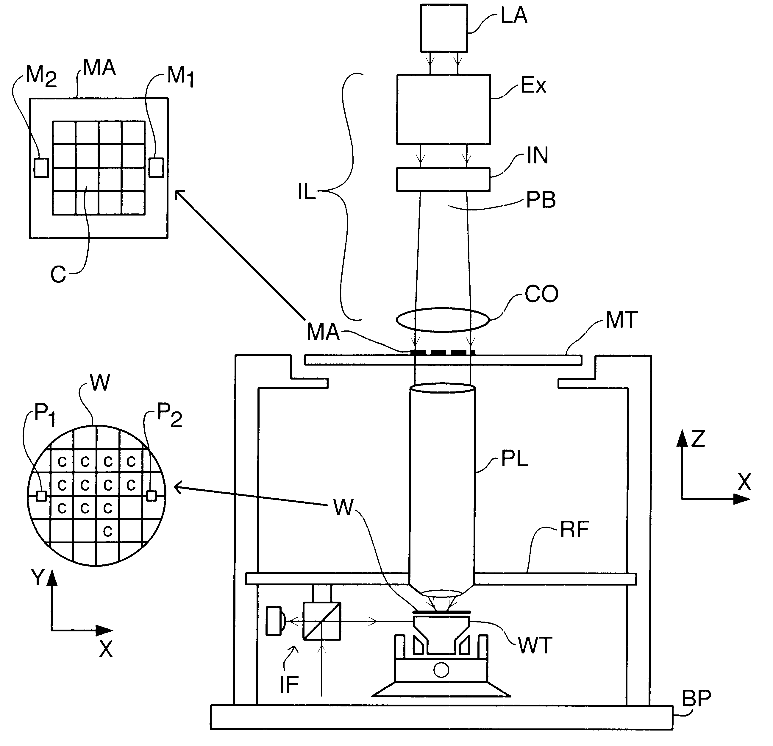
FIG. 1 schematically depicts a lithographic projection apparatus according to the invention. The apparatus comprises:

a radiation system LA, IL for supplying a projection beam PB of radiation (e.g. UV or EUV radiation, x-rays, electrons or ions);

a first object table (mask table) MT provided with a mask holder for holding a mask MA (e.g. a reticle), and connected to first positioning means for accurately positioning the mask with respect to item PL;

a second object table (substrate table) WT provided with a substrate holder for holding a substrate W (e.g. a resist-coated silicon wafer), and connected to second positioning means for accurately positioning the substrate with respect to item PL;

a projection system ("lens") PL (e.g. a refractive or catadioptric system, a mirror group or an array of field deflectors) for imaging an irradiated portion of the mask MA onto a target portion C of the substrate W.

As here depicted, the apparatus is of a transmissive type (i.e. has a transmissive m...

embodiment 2

The substrate stage, comprising substrate table WT, of a second embodiment of the invention, which may be the same as the first embodiment save as described below, is shown in FIG. 12.

In the second embodiment, the balance mass 406 takes the form of an open box with a flat interior base 407, forming a guide surface for the wafer table WT, and upstanding side walls 408 serving to raise the center of gravity of the balance mass 406. The substrate table WT includes a fine positioning mechanism 417 operating in 6 degrees of freedom for the substrate W and a so-called air-foot forming a substantially frictionless bearing allowing the substrate table WT to be moved over the guide surface 407.

Movement of the substrate table WT is effected by the coarse positioning mechanism. This includes X-beam 415 relative to which the substrate table WT is driven by an X-driver (not shown) which has at its ends sliders 411 which include the translators of Y-direction linear motors to drive the X-beam, an...

embodiment 3

FIG. 13 depicts the substrate stage, comprising substrate table WT, of a third embodiment of the invention, which may be the same as the first or second embodiments described above.

In the third embodiment, the balance mass is divided into two parts 506, 507. The first balance mass part 506 comprises a rectangular frame surrounding the substrate table WT. Opposite sides of the first balance mass part 506 have mounted thereon the stator, e.g. the magnet track, of the Y-direction linear motors. The translators, e.g. coils, of the Y-direction linear motors, are mounted in sliders 511 at the ends of X-beam 515. The X-beam includes the stator of X-linear motor and the translator is mounted to the substrate table WT. Y- and R.sub.z -reaction forces from the Y linear motor, which forms the coarse positioning mechanism together with the X-linear motor, arc transmitted directly to the first balance mass part 506 and the X-reaction forces are transmitted via thrust bearings (not shown). To abs...


PUM


Abstract

A balanced positioning apparatus comprises a balance mass which is supported so as to be moveable in the three degrees of freedom, such as X and Y translations and rotation about the Z-axis. Drive forces in these degrees of freedom act directly between the positioning body and the balance mass. Reaction forces arising from positioning movements result in corresponding movement of the balance mass and all reaction forces are kept within the balanced positioning system. The balance mass may be a rectangular balance frame having the stators of two linear motors forming the uprights of an H-drive mounted on opposite sides. The cross-piece of the H-drive spans the frame and the positioned object is positioned within the central opening of the frame.

Description

1. Field of the InventionThe present invention relates to balanced positioning systems, such as may be used to position a moveable object in at least three degrees of freedom. More particularly, the invention relates to the use of such a balanced positioning system in lithographic projection apparatus comprising:an illumination system for supplying a projection beam of radiation;a first object table for holding patterning means capable of patterning the projection beam according to a desired pattern;a second object table for holding a substrate; anda projection system for imaging the patterned beam onto a target portion of the substrate.2. Description of the Related ArtThe term "patterning means" should be broadly interpreted as referring to means that can be used to endow an incoming radiation beam with a patterned cross-section, corresponding to a pattern that is to be created in a target portion of the substrate; the term "light valve" has also been used in this context. Generall...

Claims


Application Information

Patent Timeline
IPC IPC(8): G03F7/20G12B5/00H01L21/027
CPCG03F7/70716G03F7/709G03F7/70766H01L21/027
Inventor KWAN, YIM BUN P.VAN DE WIEL, WILHELMUS J. T. P.
Owner ASML NETHERLANDS BV
Why Eureka
Try Eureka