Apparatus for the collection and distribution of liquid in a column

Inactive Publication Date: 2003-03-04
SULZER CHEMTECH AG
View PDF11 Cites 27 Cited by
  • Summary
  • Abstract
  • Description
  • Claims
  • Application Information

AI Technical Summary

Problems solved by technology

In the event of non-uniform liquid output and distribution and the resultant non-uniform wetting, maldistribution (faulty distribution) arises inside the filler body layers for example in the form of passage flow.
This quite considerably restricts the effectiveness and the function of the exchange column.
The turbulences and flow velocities resulting from this method of construction are very large in distributor inflows of this kind.
In this the problem arises that a non uniform distribution of the liquid is produced by the flow in the longitudinal direction of the distributor passages.
Furthermore, it must be remarked that the previous apparatuses for the bringing together and complete mixing of the entire back-flowing liquid after their being caught in the collector and the subsequent multiple new distribution or redistribution up to and including the fine distribution at the drip points are constructionally very complicated and e

Method used


Image

  • Apparatus for the collection and distribution of liquid in a column
  • Apparatus for the collection and distribution of liquid in a column
  • Apparatus for the collection and distribution of liquid in a column

Examples


Example

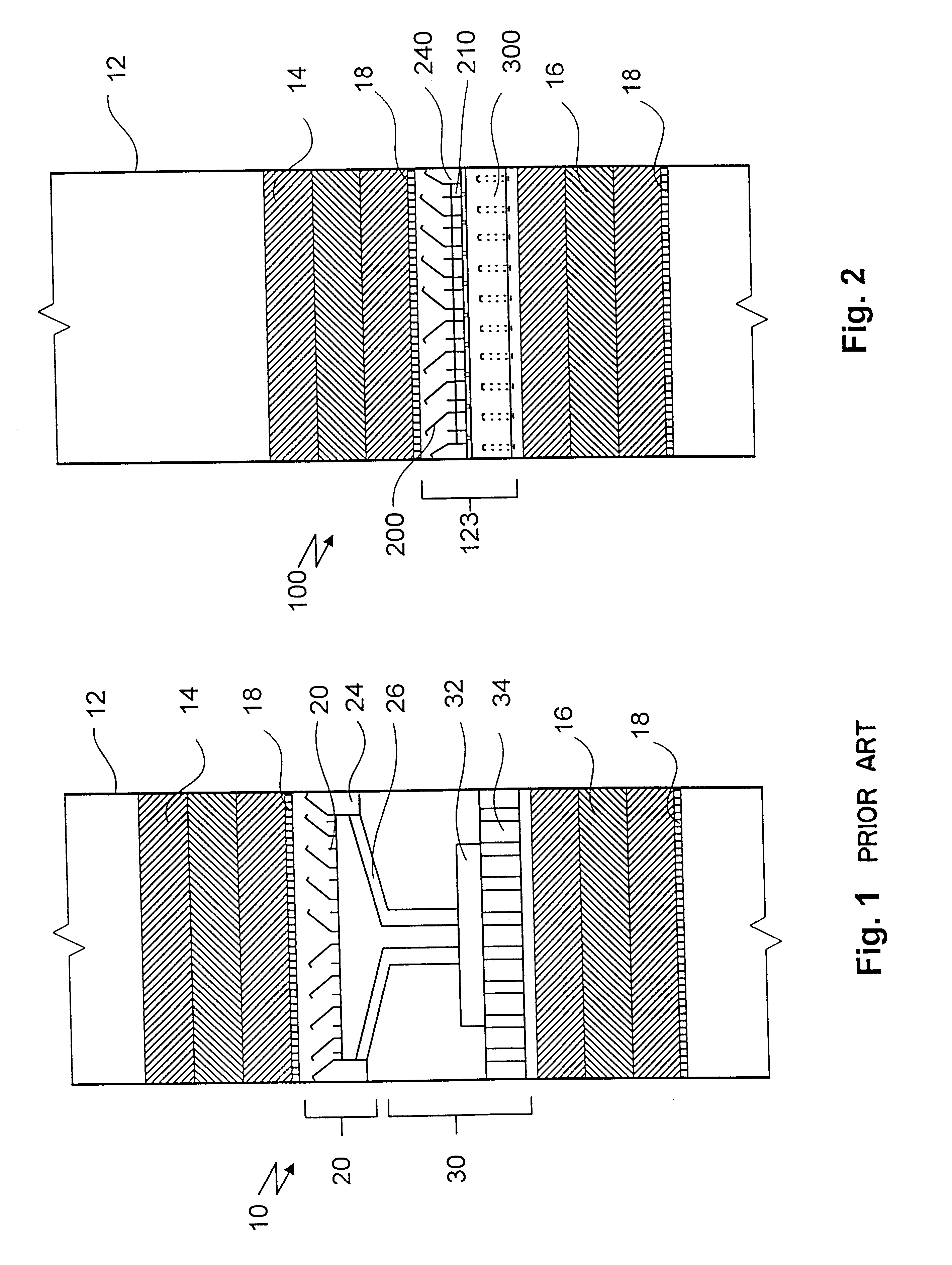
In FIG. 1 the schematic illustration of a conventional redistributor station 10 is illustrated. In this the column chute 12, the upper packing bed 14, the lower packing bed 16 and the redistributor stations placed between them can be seen. The latter consists of a collector apparatus 20 and a completely separate distributor apparatus 30. The liquid is conducted from the collector apparatus 20 to the mainly central inlet of the pre-distributor 32 or distributor 34 through at least one elongate and downwardly directed down pipe 26. Then the liquid is to be uniformly distributed over the lower packing bed 16 with the help of at least one distributor stage.

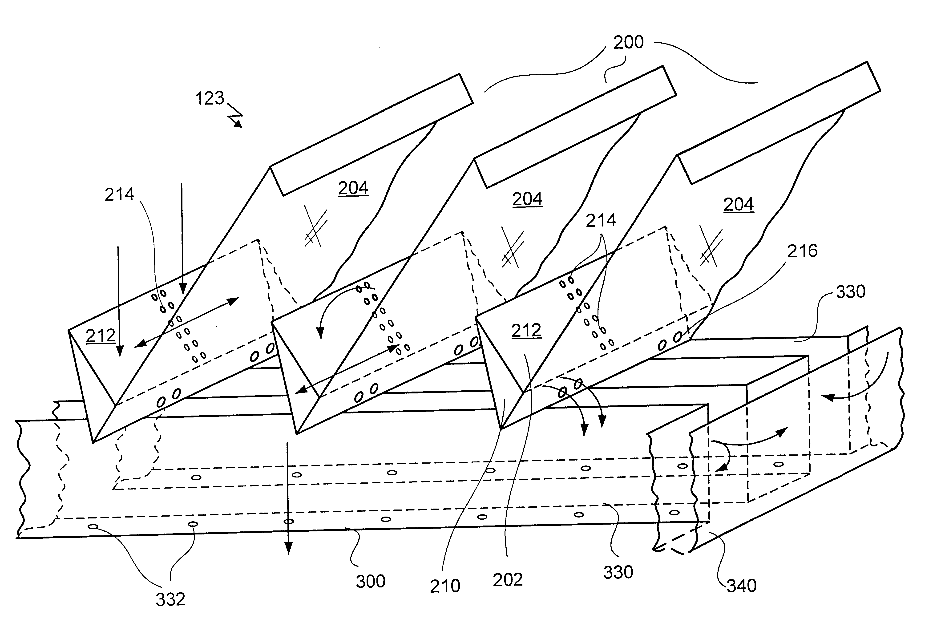
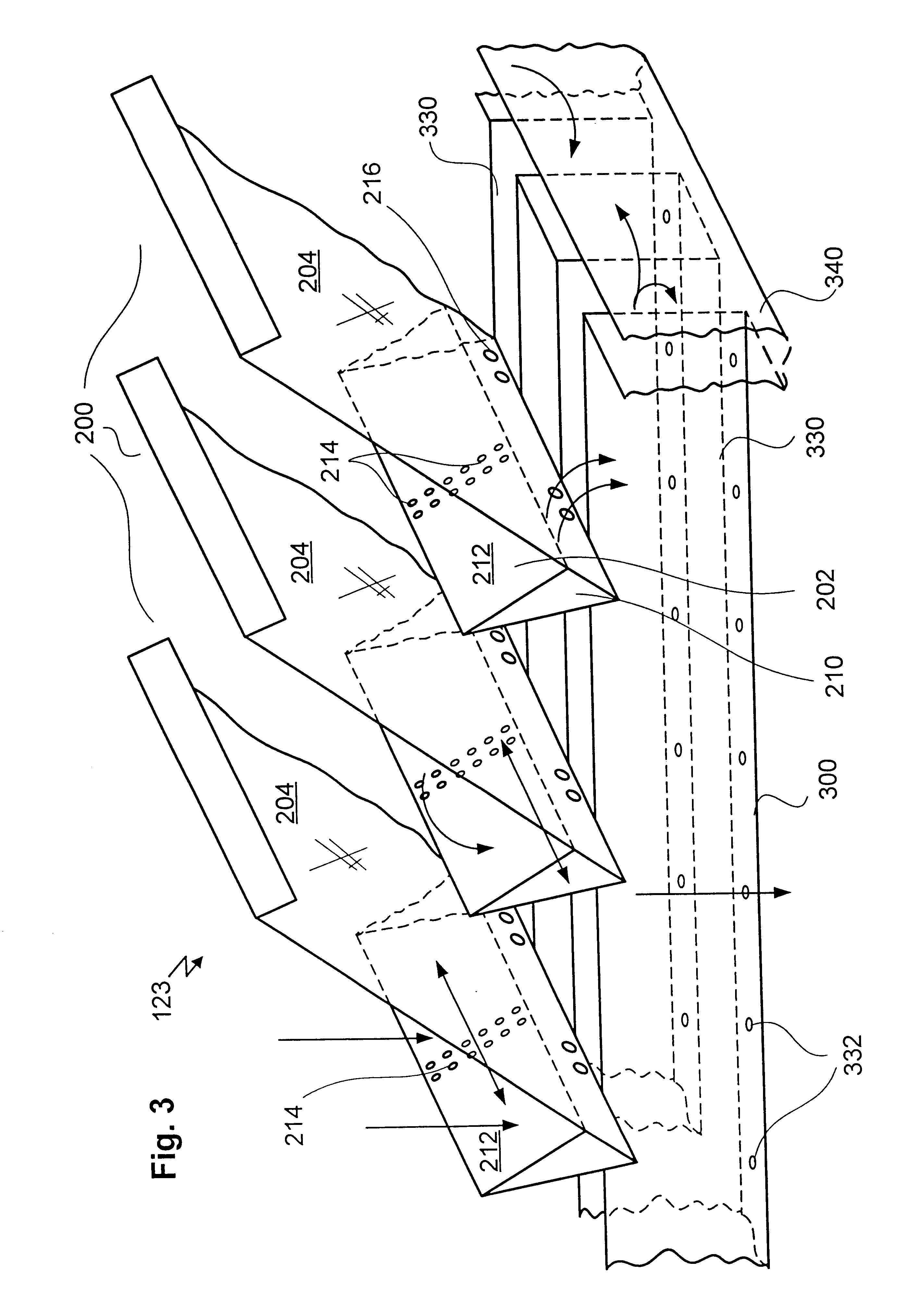
FIG. 2 is the schematic illustration of a redistributor station 100 with a compact collector and distributor apparatus 123 in accordance with the invention. The illustration comprises the column chute 12, as in FIG. 1, an upper and lower packing bed 14 and 16. The reduction of the space between the upper and lower packing bed in compa...


PUM

PropertyMeasurementUnit
Fractionaaaaaaaaaa
Lengthaaaaaaaaaa
Diameteraaaaaaaaaa

Abstract

The apparatus for the collection and distribution of liquid in a column having at least one lamella collector and a distributor outflow system which is arranged below it. A side passage is contained in the or in each lamella collector and liquid outflow openings are arranged in a combination, as a result of which a hydrodynamic equalization for a liquid to be distributed results.

Description

1. Field of the InventionThe present invention relates to an apparatus for the collection and distribution of liquid in a column. In this a plurality of unordered or ordered packings are located in the column in each case on a carrier grid, beneath which the apparatus for the collection and distribution of liquid is arranged.2. Description of the Prior ArtIn material exchange columns of this kind the packing or the filling body is supported by a carrier grid, with the liquid dripping off over this carrier grid and being caught, mixed and conducted to the new distribution or redistribution respectively or to the liquid removal.Field of application is preferably the material separation technique such as the absorption and desorption in fluid systems, the distillation and rectification and the technical carrying out of reactions at catalyst layers. For several years it has been usual to use non ordered filler bodies or packings, in particular structured or ordered packings respectively...

Claims


Application Information

Patent Timeline
IPC IPC(8): B01D3/00B01D3/32B01D3/16
CPCB01D3/008
Inventor BARTLOK, GUIDO
Owner SULZER CHEMTECH AG
Why Eureka
Try Eureka