Solar battery module arranging method and solar battery module array

a solar battery and module array technology, applied in the field of solar battery module array arranging method and solar battery module array, can solve the problems of poor outer appearance, difficult electrical wiring, and degraded roof appearan

Inactive Publication Date: 2003-03-18
CANON KK
View PDF10 Cites 93 Cited by
  • Summary
  • Abstract
  • Description
  • Claims
  • Application Information

AI Technical Summary

Problems solved by technology

1. Since a roofing material integrated solar battery module cannot be cut, the setting place for the roofing material integrated solar battery modules is limited. For, e.g., a hip roof, the allowable setting range narrows from the eaves to the ridge, so a number of roofing material integrated solar battery modules cannot be arranged.
2. When the roofing material integrated solar battery modules are not regularly arranged, the outer appearance of the roof is degraded.
3. Electrical wiring is difficult.
Additionally, since the solar battery modules are irregularly arranged (FIG. 5), the outer appearance is not good (the above-mentioned problem 2).
In the arranging methods shown in FIGS. 4 and 5, since the distance between roofing material integrated solar battery modules 401 on adjacent lines is large, a lot of connection cables 406 are required to connect the connectors of the solar battery modules, resulting in low execution efficiency and high cost (the above-mentioned problem 3).
However, in actual execution, it is impossible to accurately align the center of the solar battery module group to the central line 107, and an error of several to several ten millimeters occurs.

Method used


Image

  • Solar battery module arranging method and solar battery module array
  • Solar battery module arranging method and solar battery module array
  • Solar battery module arranging method and solar battery module array

Examples


third embodiment

[Third Embodiment]

FIG. 12 is a view showing a state wherein the above-described roofing material integrated solar battery modules SR-02 are arranged in an allowable setting range 1202 on a triangular roof whose eaves 1204 have a length L1 of 9,200 mm and roof inclination has a length A1 of 5,050 mm in accordance with the procedure shown in the flow chart of FIG. 22 while setting a gap g1 from the eaves 1204 to the allowable setting range 1202 to be 0 mm, and a gap g3 from a roof boundary 1205 to the allowable setting range 1202 to be 200 mm. The setting procedure will be briefly described below. The same numbers as in FIG. 19 denote the same steps in the flow chart of FIG. 22, and a detailed description thereof will be omitted.

[Calculation of Maximum Setting Number of Lines (Steps S1 to S3)]

A length A of the allowable setting range 1202 in the inclination direction is given by:

A=A1-g1=5,050-200=4,850 mm

The number C of lines is given by the following inequality, and a maximum setting...

fourth embodiment

[Fourth Embodiment]

FIG. 15 is a view showing a state wherein frame mounted solar battery modules (W=822 mm, and .lambda.=1,220 mm) are arranged in an allowable setting range 1502 on a trapezoidal roof whose eaves 1504 have a length L1 of 12,000 mm, ridge 1506 has a length L2 of 3,640 mm, and roof inclination has a length A1 of 4,957 mm in accordance with the procedure shown in the flow chart of FIG. 20 while setting a gap g1 from the eaves 1504 to the allowable setting range 1502 to be 500 mm, a gap g2 from the ridge 1506 to the allowable setting range 1502 to be 500 mm, and a gap g3 from a roof boundary 1505 to the allowable setting range 1502 to be 300 mm. The setting procedure will be briefly described below.

[Calculation of Maximum Setting Number of Lines (Steps S1 to S3)]

A length A of the allowable setting range 1502 in the inclination direction is given by:

A=A1-g1-g2=4,957-500-500=3,957 mm

The number C of lines is given by the following inequality, and a maximum setting number C...

fifth embodiment

[Fifth Embodiment]

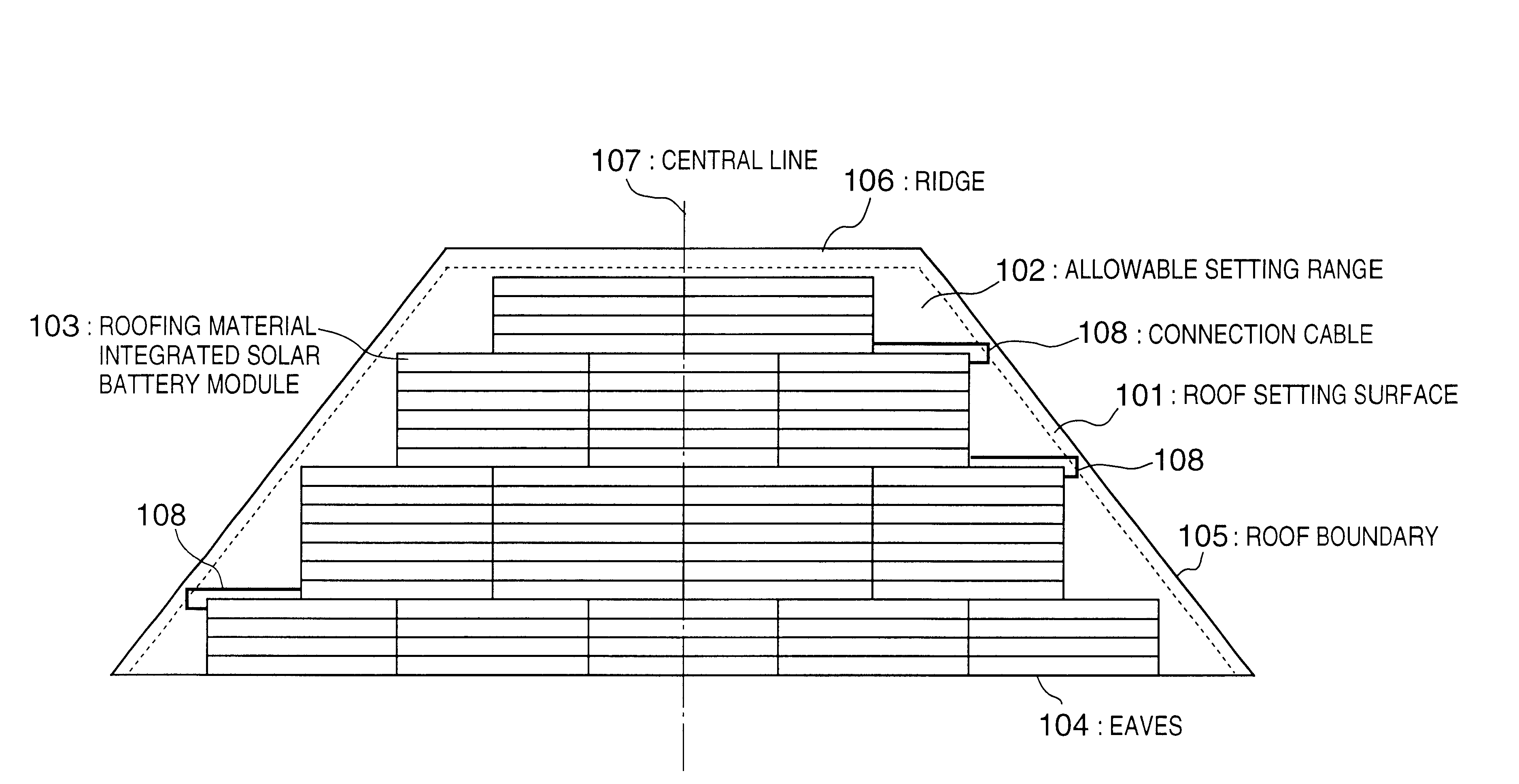
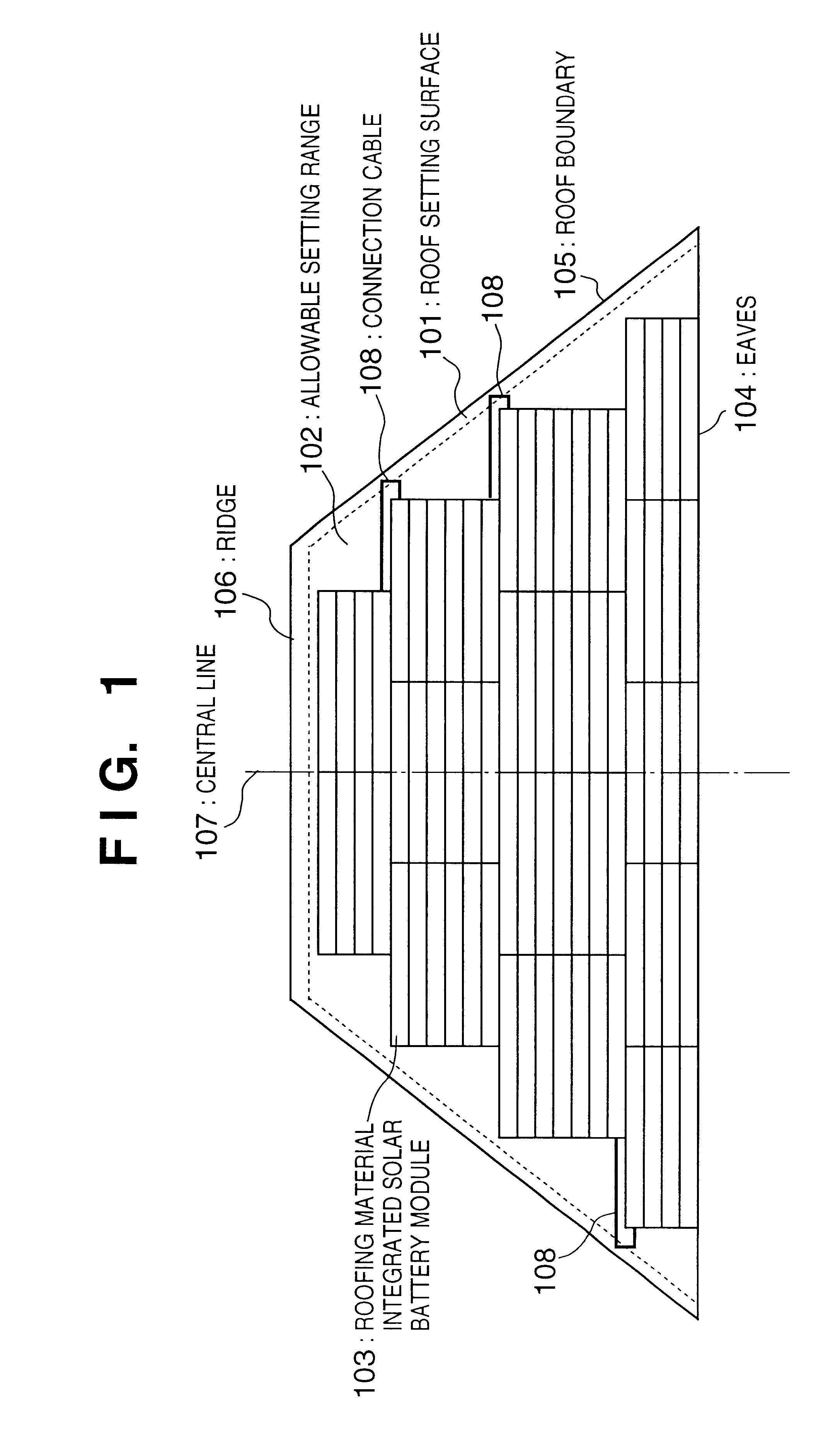
FIG. 17 is a view showing a state wherein the above-described roofing material integrated solar battery modules SR-02 are arranged on an Irimoya-type roof whose eaves 1704 has a length L1 of 9,000 mm, ridge 1706 has a length L2 of 5,000 mm, roof inclination direction of the trapezoidal portion has a length A1 of 1,390 mm, and roof inclination of the rectangular portion has a length A2 of 2,570 mm in accordance with the procedure shown in the flow chart of FIG. 23 while setting gaps g1 to g3 from the eaves 1704, ridge 1706, and roof boundary 1705 to the allowable setting range to be 200 mm. The same numbers as in FIG. 19 denote the same steps in the flow chart of FIG. 23, and a detailed description thereof will be omitted. The "Irimoya-type roof" means that the upper portion of one roof surface is formed into a gable, and roof surfaces are formed at the four lower sides of the lower portions.

[Calculation of Maximum Setting Number of Lines (Steps S1 to S3)]

A length A...


PUM


Abstract

To optimally arrange roofing material integrated solar battery modules having a rectangular form and same size on a roof setting surface, an arrangement range in which the solar battery modules can be arranged on the roof setting surface is determined. An arranging direction of the solar battery modules is determined. The number of solar battery modules which can be arranged almost horizontally in a line in the determined arranging direction and within the arrangement range is calculated. Solar battery modules of a line in a number not more than the calculated number are combined to form a solar battery module group. The solar battery module groups are arranged to set a center of the solar battery module group within the determined arrangement range and near a line almost vertically dividing the surface into two parts. The above operations are repeated a number of times corresponding to the number of lines of solar battery module groups which can be vertically arranged in the determined arranging direction and within the arrangement range.

Description

1. Field of the InventionThe present invention relates to a solar battery module arranging method and a solar battery module array and, more particularly, to an arranging method for arranging solar battery modules having a rectangular form and same size on a setting surface such as a roof, and a solar battery module array arranged by the arranging method.2. Description of the Related ArtAs a method for arranging a roofing material and, more specifically, a stepping roof or Bermuda-type roof material on a roof surface, the dutch-lap method (FIG. 2) or the Mechigai-roofing method / shift-roofing method (FIG. 3) is used. These roofing material arranging methods are advantageous in obtaining a good outer appearance because roofing materials 201 are arranged at a predetermined joint shift width 205 from eaves 202 at the lower end side of the roof to a ridge 203 as at the upper end side of the roof. In these arranging methods, for weathering, the joint portions are shifted at a period corre...

Claims


Application Information

Patent Timeline
Patent Type & Authority Patents(United States)
IPC IPC(8): H01L31/048E04D1/00E04D1/30E04D3/40E04D13/18F24J2/04F24J2/52H01L31/042
CPCF24J2/5211H01L31/048H02S20/23F24J2/045Y02B10/12Y02E10/47Y02E10/50Y10S136/291Y10S126/906Y02B10/20F24S20/67F24S25/20F24S2201/00Y02B10/10E04D13/00
Inventor MAKITA, HIDEHISAFUKAE, KIMITOSHITAKABAYASHI, AKIHARUSHIOMI, SATORUITOYAMA, SHIGENORI
Owner CANON KK
Why Eureka
Try Eureka