Method and apparatus for high speed electron beam rapid prototyping

Inactive Publication Date: 2003-03-25
NORTH STAR POWER ENG
View PDF18 Cites 79 Cited by
  • Summary
  • Abstract
  • Description
  • Claims
  • Application Information

AI Technical Summary

Benefits of technology

is to create parts with such great rapidity that it c

Problems solved by technology

Present rapid prototyping technologies, as disclosed in U.S. Pat. No. 4,575,330 to Hull and U.S. Pat. No. 4,929,402 to Hull, use lasers or powder streams at high cost, and with slow processing rates.
Such a part will cost in excess of $1000.
O

Method used


Image

  • Method and apparatus for high speed electron beam rapid prototyping
  • Method and apparatus for high speed electron beam rapid prototyping
  • Method and apparatus for high speed electron beam rapid prototyping

Examples


Example

)

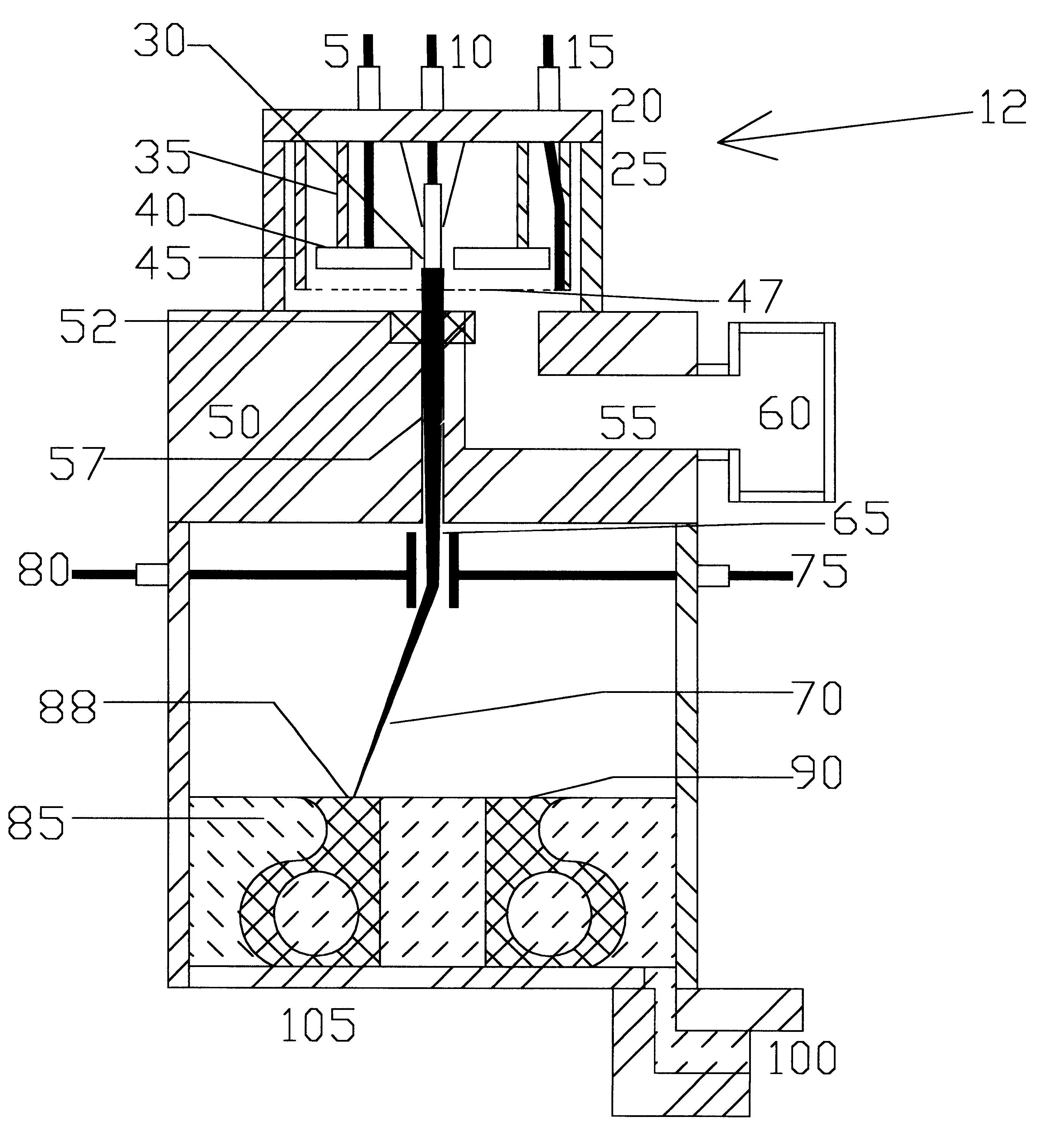
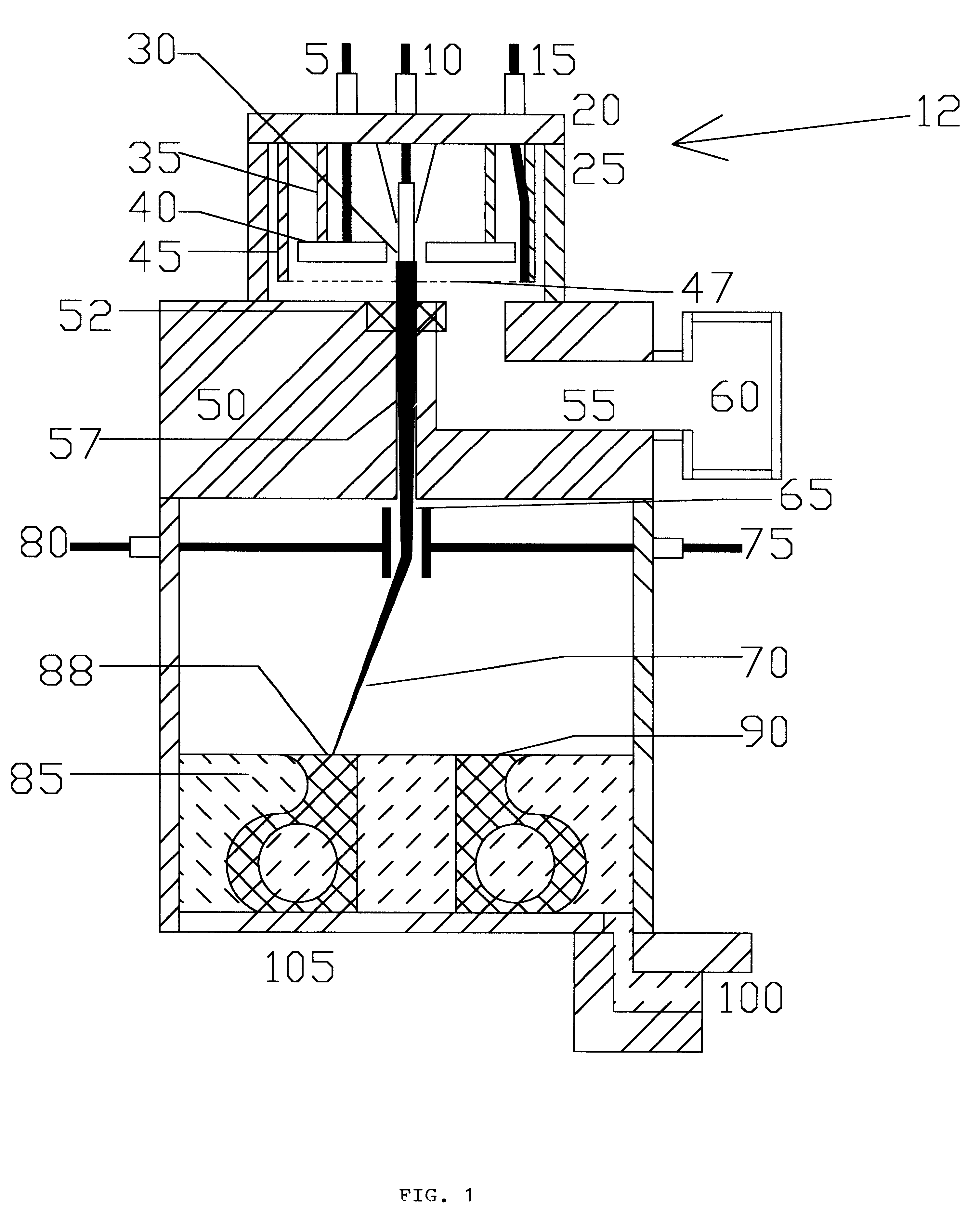
The use of an electron beam system for the fabrication process is superior to lasers and other existing rapid prototyping processes. In this process, the material in the rapid prototyping system is built up from liquid by using an electron beam to cure (i.e. instantaneously solidify through initiation of chemical reactions which lengthen polymer chains) a liquid.

The specific energy required to cure material is well established in the literature as approximately 5 Megarads (50 J / g). Ideally, a 200 W beam (100 kV, 2 mA) can solidify 4 g / sec, or about 4 cc / sec excluding voids. With a void fraction of 50% this volume rises to 8 cc / sec, and higher powers than 50 J / sec are possible. At this rate, a medium sized, complex assembly which is half solid (say, 6".times.6".times.12") can be built up in 10 minutes. This is a factor of about 40 times faster than existing technology. The electron beam cure does not require photo initiators which a laser requires, therefore plastics with superior p...


PUM

PropertyMeasurementUnit
Electric potential / voltageaaaaaaaaaa
Thicknessaaaaaaaaaa

Abstract

An electron beam as a curing technique with dynamic beam control technology in order to produce arbitrarily shaped parts. The result of this is equipment which can create prototypes and parts rapidly without additional tooling. The electron beam from a low divergence gun is accelerated towards uncured monomer in vacuum. Deflection of the beam combined with a grid which is used to turn the beam on and off, creates a two dimensional curing path with a depth of approximately five (5) thousandths of inch. Successive layers of this type, built up as monomer is added, creates a three dimensional pattern. The layers can either be of uniform thickness, or can be varied in thickness by varying the energy of the beam.

Description

1. Field of the Invention (Technical Field)The invention relates to manufacturing three dimensional objects, and more particularly to an apparatus and method of forming three dimensional objects from a fluid medium using a high speed electron beam to harden the fluid medium in a predetermined pattern.2. Background ArtRapid prototyping is the technology of creating arbitrarily shaped parts. In general, this technology has the ability to produce enclosed volumes (like a can) in contrast to such processes as multi-axis milling which can only produce simply connected volumes (like a cup instead of a can, which is simply connected to the outside of the cup). If this technology is fast and accurate enough it can replace a variety of other techniques such as molding, and in many cases eliminate bonding of multiple pieces of material.Present rapid prototyping technologies, as disclosed in U.S. Pat. No. 4,575,330 to Hull and U.S. Pat. No. 4,929,402 to Hull, use lasers or powder streams at hi...

Claims


Application Information

Patent Timeline
IPC IPC(8): B29C67/00B29C35/08
CPCB29C67/0066B29K2105/0002B29C2035/0877B33Y30/00B29C64/135
Inventor ADLER, RICHARD J.
Owner NORTH STAR POWER ENG
Why Eureka
Try Eureka