Most such apparatus and systems are either bulky in size, complex to manufacture and some allow the reentry of gas bubbles or sediment into the intravenous (IV) line under a sudden move of patient's limb.
Such current devices also falter when employed in the field under rough handling and transport conditions such as during a disaster, a
battlefield or when administering transfusion in a helicopter.
It is also known that there exist a common
hazard associated with the injection of fluid into the veins of a human or animal when gas bubbles and sediment enter the body.
This operation is time-consuming and often painful and dangerous to the patient.
If air bubbles enter the
vein with the injection liquid, an air
embolus is produced, usually resulting in
severe pain to the patient, and if allowed to continue even for several seconds, the patient may receive a dangerous or fatal amount of air.
The repeated purging of air from the tubing which connects the injection needle to the liquid supply results in a loss of valuable medicinal material, and as usually performed, the medicinal liquid is sprayed over the floor and on equipment in the room where the patient is being treated.
There are a number of approaches advanced in prior art, however such prior art still leave problems regarding the size of apparatus, the ease of manufacture of devices which ultimately affects the cost of the apparatus and most importantly the heath risk involved with the reentry of bubbles and sediment into the intravenous injection fluid.
However, prior art addresses only partially these issues leaving a constant
hazard to users of such devices.
Bauer's device is cumbersome in size and causes a major
health risk factor if the bulging space is turned upside-down or otherwise displaced in the
wrong direction.
However, the removal of gas or bubbles from a transfusion liquid is not necessarily complete in such devices.
In addition, The device is difficult to manufacture and has the same
disadvantage than Bauer, it fails to prevent sediment and air bubbles to reenter the intravenous line if positioned anywhere but upright.
The bubble
elimination port closes to the fluid circuit after tube connections are done and thus does not provide a trap for trapping incoming gas bubbles or solids on an ongoing basis.
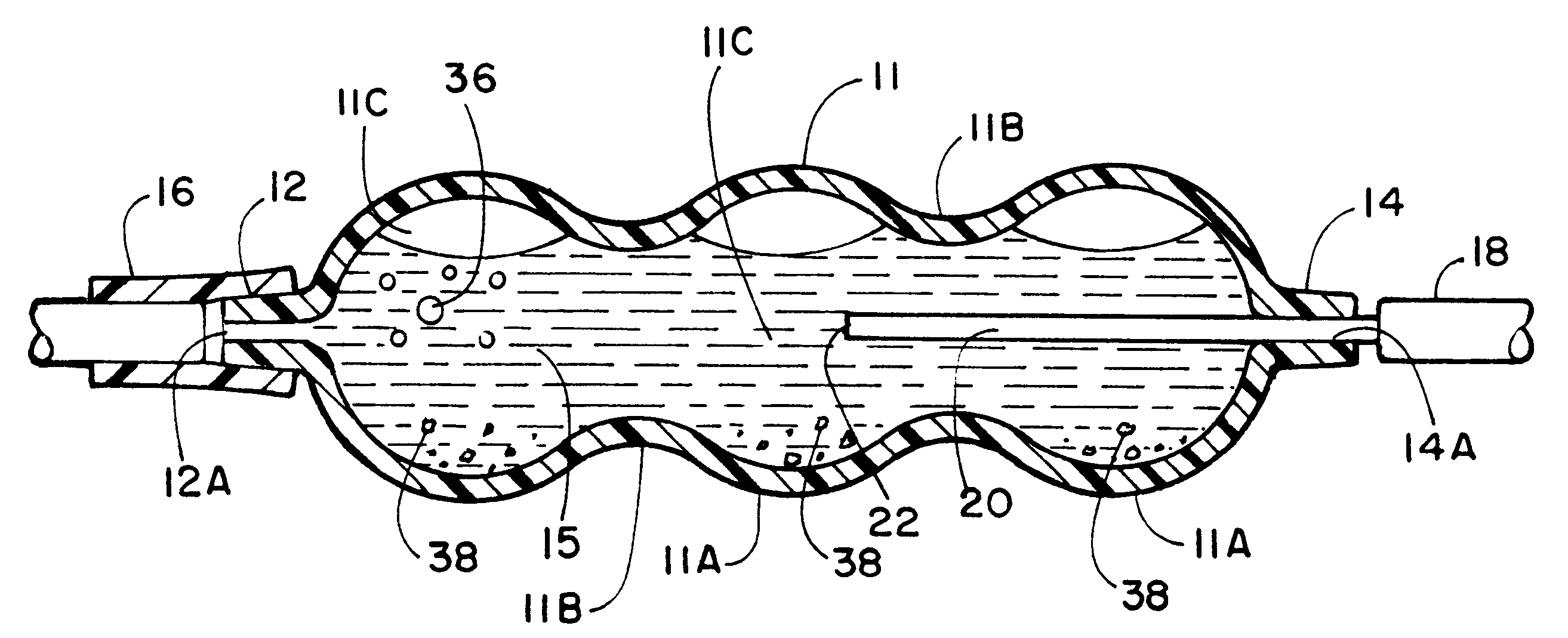
In most above mentioned devices, drawbacks are encountered that sudden changes in position of the patient's limb cause air bubbles and sediment to be entrained back into the line and ultimately to the patient.
Depending on the density and
viscosity of each
intravenous fluid, the aperture
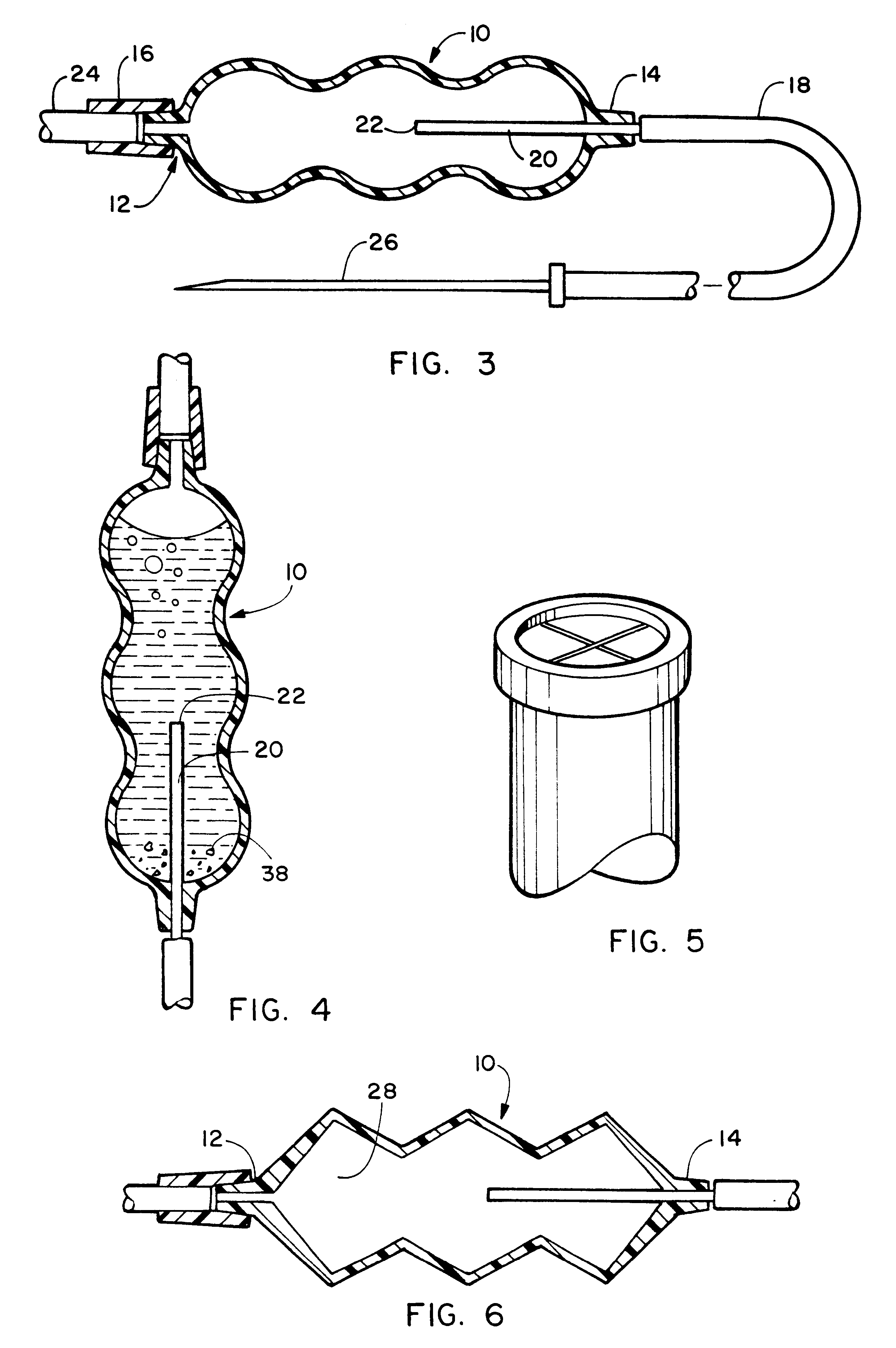
diameter of outlet tube may also be provided with a cross-hair partition ring reducing further the size of said diameter aperture, thus impeding further any possibility for bubbles to exit the trap.

