Multi-loop phase lock loop for controlling jitter in a high frequency redundant system

a phase lock and redundant system technology, applied in the field of timing circuitry, can solve problems such as difficulty in the receiving system to obtain the acquisition ("lock") of the newly acquired clock signal, and the switching between high-frequency primary and redundant clock signals

Inactive Publication Date: 2003-03-25
JUMIPER NETWORKS INC
View PDF5 Cites 39 Cited by
  • Summary
  • Abstract
  • Description
  • Claims
  • Application Information

AI Technical Summary

Problems solved by technology

Problems can arise when switching between high-frequency primary and redundant clock signals and when initially turning on the high-frequency clock signal.
The high frequency of the clocks can make it difficult for the r

Method used


Image

  • Multi-loop phase lock loop for controlling jitter in a high frequency redundant system
  • Multi-loop phase lock loop for controlling jitter in a high frequency redundant system
  • Multi-loop phase lock loop for controlling jitter in a high frequency redundant system

Examples


Embodiment Construction

refers to the accompanying drawings. The same reference numbers in different drawings identify the same or similar elements. Also, the following detailed description does not limit the invention. Instead, the scope of the invention is defined by the appended claims and equivalents.

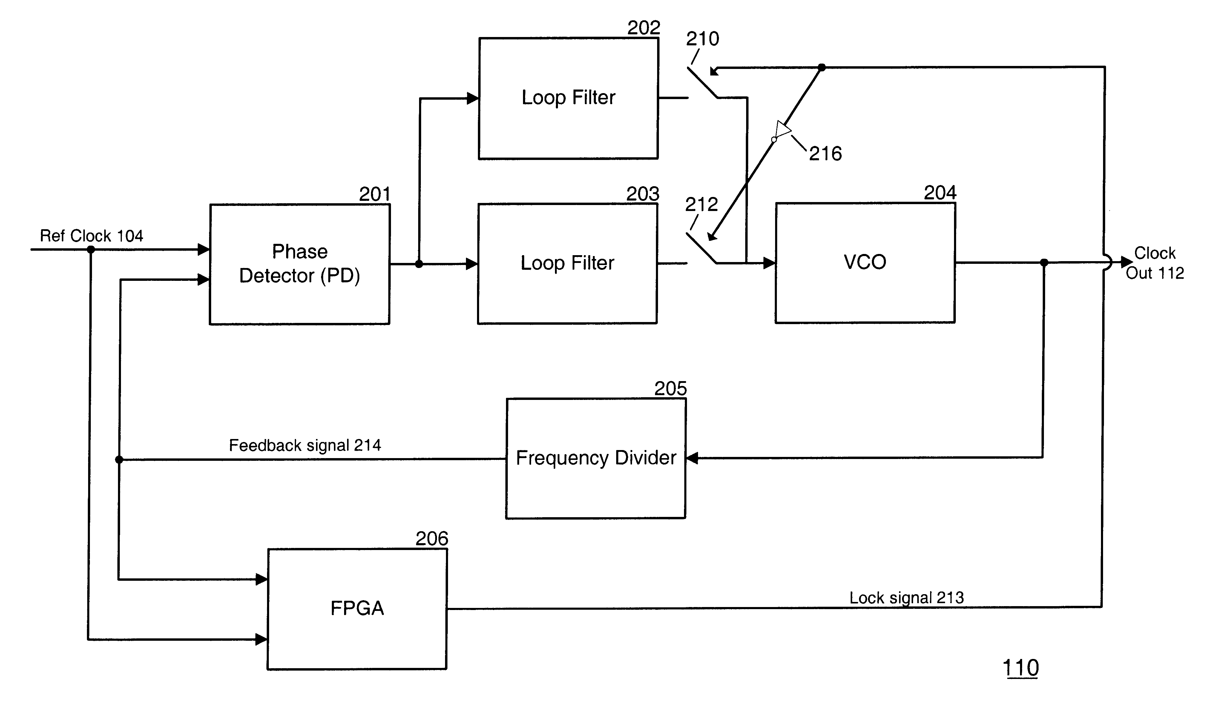
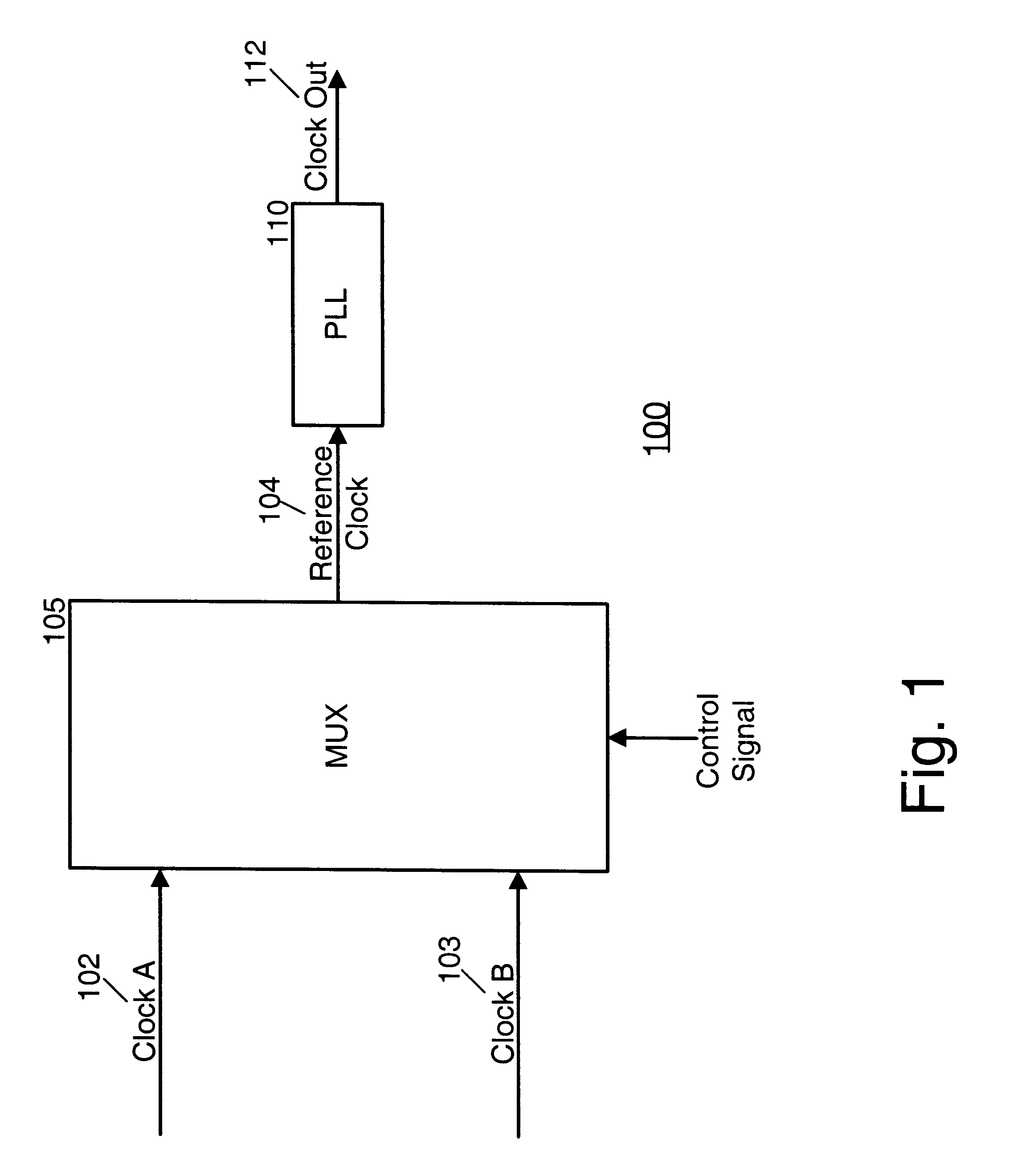
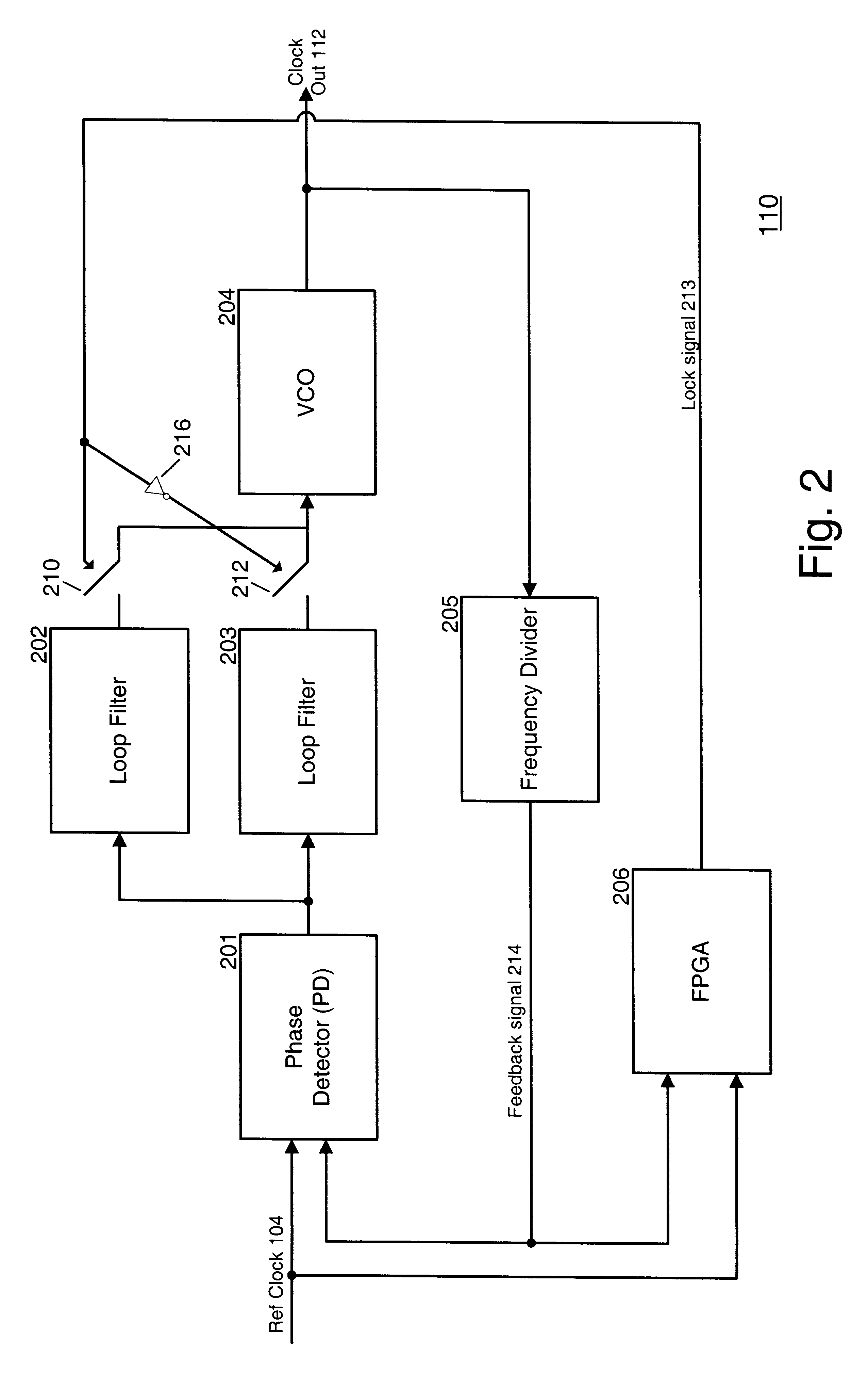
As described herein, a multi-loop phase lock loop (PLL), containing multiple phase locked loop filters, each having different bandwidths, receives one of multiple high-frequency clock signals as an input. During clock start-up or upon a clock switch over sequence, the multi-loop PLL uses the wide bandwidth loop to quickly lock the input clock signal. Once the clock signal is locked, a narrower bandwidth loop filter in the PLL can then reduce jitter in the locked signal. Alternatively, during a clock switch over, if the new clock signal is enough in phase to the old clock signal, the multi-loop PLL may immediately use the narrow band PLL to reduce jitter.

FIG. 1 is a block diagram illustrating, at a high lev...


PUM


Abstract

A multi-loop phase lock loop (PLL) contains multiple loop filters, each having different bandwidths. The multi-loop PLL receives one of multiple high-frequency clock signals as an input. A phase detector outputs a signal, based on the phase difference between the high-frequency clock signal and a feedback signal to the loop filters. A voltage controlled oscillator generates an output clock signal based on signals received from the loop filters. During a clock switch over sequence between the multiple high-frequency input clock signals, the multi-loop PLL uses one of its loop filters with a wide bandwidth to quickly lock the input clock signal. Once the clock signal is locked, a narrower bandwidth loop filter in the PLL is then used to reduce jitter in the locked signal.

Description

A. Field of the InventionThe present invention relates generally to timing circuitry, and more particularly, to circuitry for high frequency clock alignment and switching.B. Description of Related ArtSynchronous circuits are circuits that perform operations in step with a clock signal. For example, a clock source can be used in conjunction with a communication bus to provide a synchronous communications link between a sourcing device and one or more receiving devices. In a source synchronous communications link, the source device provides a source clock signal that the receiving device uses to synchronize the reading of data from the communications link.Designs for mission critical systems must provide reliability. Redundancy can be built into a mission critical system to increase reliability. For example, redundant timing signals may be used in high performance telecommunications systems, such as high performance network routers. Such systems may include systems that have redundant...

Claims


Application Information

Patent Timeline
IPC IPC(8): H03L7/08H03L7/107H04J3/06H03L7/095
CPCH04J3/0688H03L7/107H03L7/095Y10S331/02H03L7/1075
Inventor CHENGSON, DAVID
Owner JUMIPER NETWORKS INC
Why Eureka
Try Eureka