
Step-down constant-current transformer

a constant-current transformer and step-down technology, applied in the direction of electric variable regulation, process and machine control, instruments, etc., can solve the problems of gap interruption operation, output ripple increase, efficiency level deterioration,

Inactive Publication Date: 2003-04-01
ROBERT BOSCH GMBH
View PDF13 Cites 121 Cited by
  • Summary
  • Abstract
  • Description
  • Claims
  • Application Information

AI Technical Summary

Benefits of technology

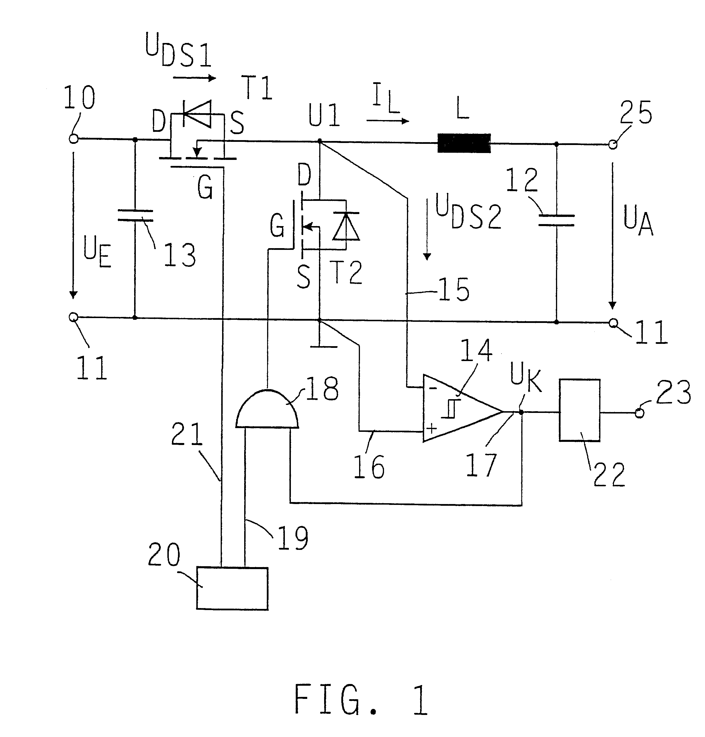
The step-down constant-current transformer configured in accordance with the present invention has the advantage of ensuring the detection of an occurrence of a reverse current using simple means and of creating the opportunity to prevent or stop the flow of this reverse current.
In an additional improvement of this exemplary embodiment, a capacitor between the positive input and the zero potential is provided in parallel upstream from the controllable, series-connected MOSFET transistor. As a result of this input capacitor, the input d.c. voltage is smoothed and overvoltage protection is achieved.

Problems solved by technology

One difficulty with these known step-down constant-current transformers is the so-called gap interrupted operation, when the output current is smaller than half of the average load current.
This problem occurs particularly in the case of step-down constant-current transformers, where the parallel-connected free-wheeling diode is replaced by a controllable switch to increase the efficiency level and to form a synchronous rectifier.
As such, this causes the efficiency level to deteriorate and the output ripple to increase.
However, in this case, a reduction of the output signal range may be unavoidable, since the measuring amplifier indicates the positive and the negative current range.
This is particularly disadvantageous for circuits that are operated using a unipolar voltage supply in motor vehicles, for example.

Method used


Image

  • Step-down constant-current transformer
  • Step-down constant-current transformer
  • Step-down constant-current transformer

Examples


Embodiment Construction

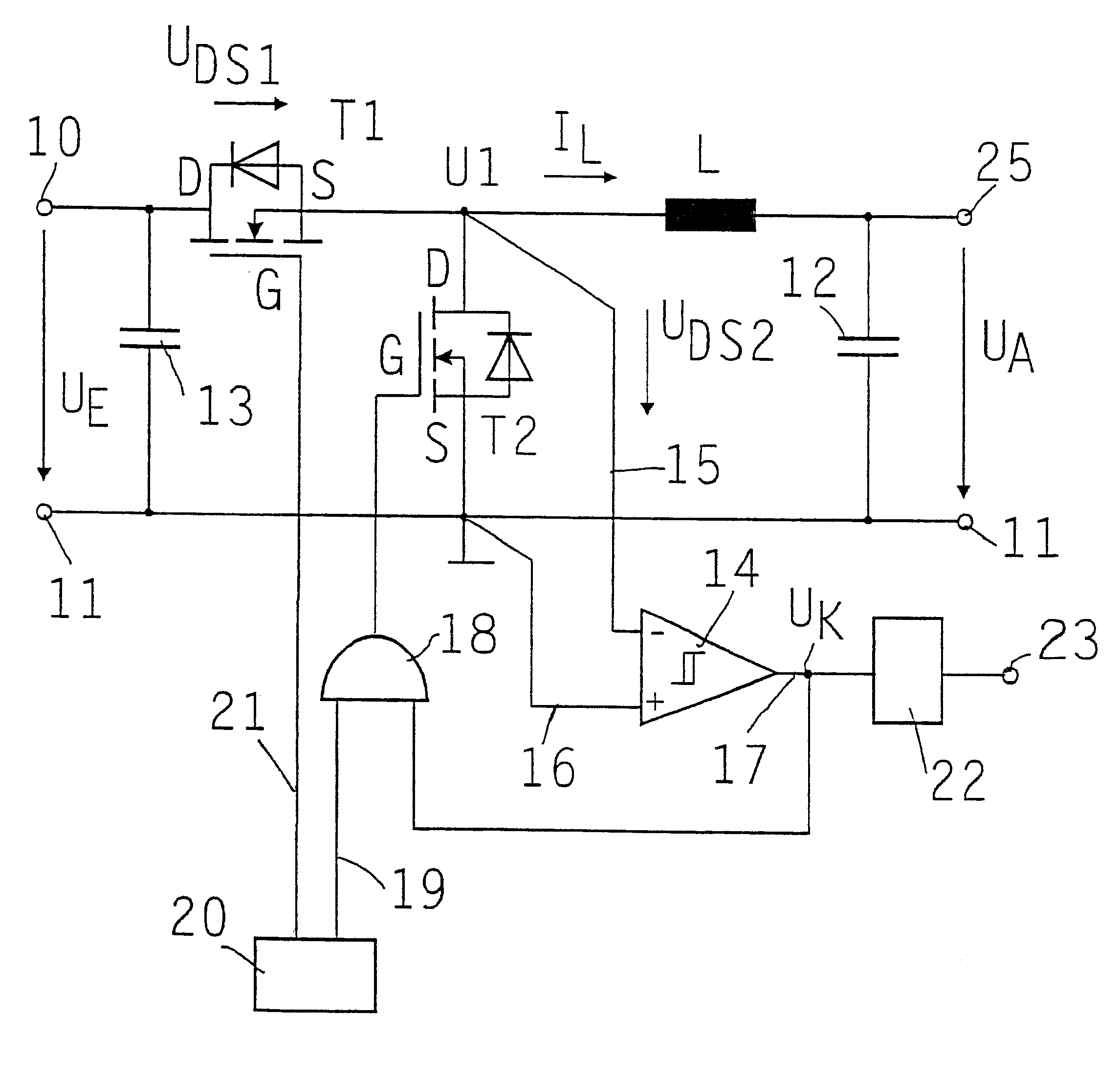
An exemplary embodiment is represented in FIG. 1 based on the schematic basic circuit diagram. The step-down constant-current transformer configured in accordance with the present invention includes a controllable switch T1 connected in series to a choke L. The series arm extends between first input 10 and an output 25. An input d.c. voltage U.sub..epsilon. is applied between first input 10 and second input 11. This input d.c. voltage U.sub..epsilon. can be the battery voltage of a motor vehicle, for example. Second input 11 is set to zero potential, for example, and also forms the second output pole in the represented exemplary embodiment. An output d.c. voltage U.sub.A is applied between output 25 and pole 11, across intermediate capacitor 12, which is provided in parallel at output 25 and is also referred to as output capacitor. A second controllable switch T2 is provided in parallel upstream from choke L. Furthermore, a capacitor 13, also referred to as the input capacitor, is p...


PUM


Abstract

A step-down constant-current transformer including a controllable switch downstream from the one input and connected in series to a choke, a capacitor connected in parallel at the output, and upstream from the choke, a second controllable switch in parallel. Both controlled switches are MOSFET transistors. A control unit, in particular a pulse-width control unit, is provided for the MOSFET transistors. The voltage across the parallel-connected MOSFET transistor is monitored to determine whether a reverse current, i.e., a current flowing through the choke from the output in the direction of the input of the constant-current transformer, or an electric potential at the center tap of the half-bridge formed by the two MOSFET transistors is detected. For this purpose, a comparator and an AND circuit are provided, which, in the event of such a reverse current, block the parallel-connected MOSFET transistor to prevent the reverse current.

Description

BACKGROUND INFORMATIONThe present invention relates to a step-down constant-current transformer, including a controllable switch downstream in outgoing circuit from the one input and connected in series to a choke, and a capacitor connected in parallel at the output, of the species defined in the first part claim 1.A step-down constant-current transformer including a controllable switch downstream from the one input, connected in series to a choke inductor, and a capacitor connected in parallel at the output, is known from the book "Halbleiter-Schaltungstechnik" (Semiconductor-Circuit Engineering) chapter 18.6.1, pp. 563-566, by U. Tietze and Ch. Schenck, Springer-Verlag publishers, 9, ed. 1989, a free-wheeling diode being provided in parallel, upstream in incoming circuit from the choke. The step-down constant-current transformer is used for converting an input d.c. voltage into another, lower output d.c. voltage. Due to its simple construction and high level of efficiency, this tr...

Claims


Application Information

Patent Timeline
IPC IPC(8): H02M3/158H02M3/04H02M3/155H02M7/21
CPCH02M3/1588Y02B70/1466Y02B70/10
Inventor DITTMER, BERNDGRONBACH, ROMAN
Owner ROBERT BOSCH GMBH
Learn More