Hybrid transmission, especially for motor vehicles

Inactive Publication Date: 2003-05-06
ROBERT BOSCH GMBH
View PDF12 Cites 173 Cited by
  • Summary
  • Abstract
  • Description
  • Claims
  • Application Information

AI Technical Summary

Problems solved by technology

A disadvantage of such power branching, however, is the incident losses.
A disadvantage is the relatively

Method used


Image

  • Hybrid transmission, especially for motor vehicles
  • Hybrid transmission, especially for motor vehicles
  • Hybrid transmission, especially for motor vehicles

Examples


Example

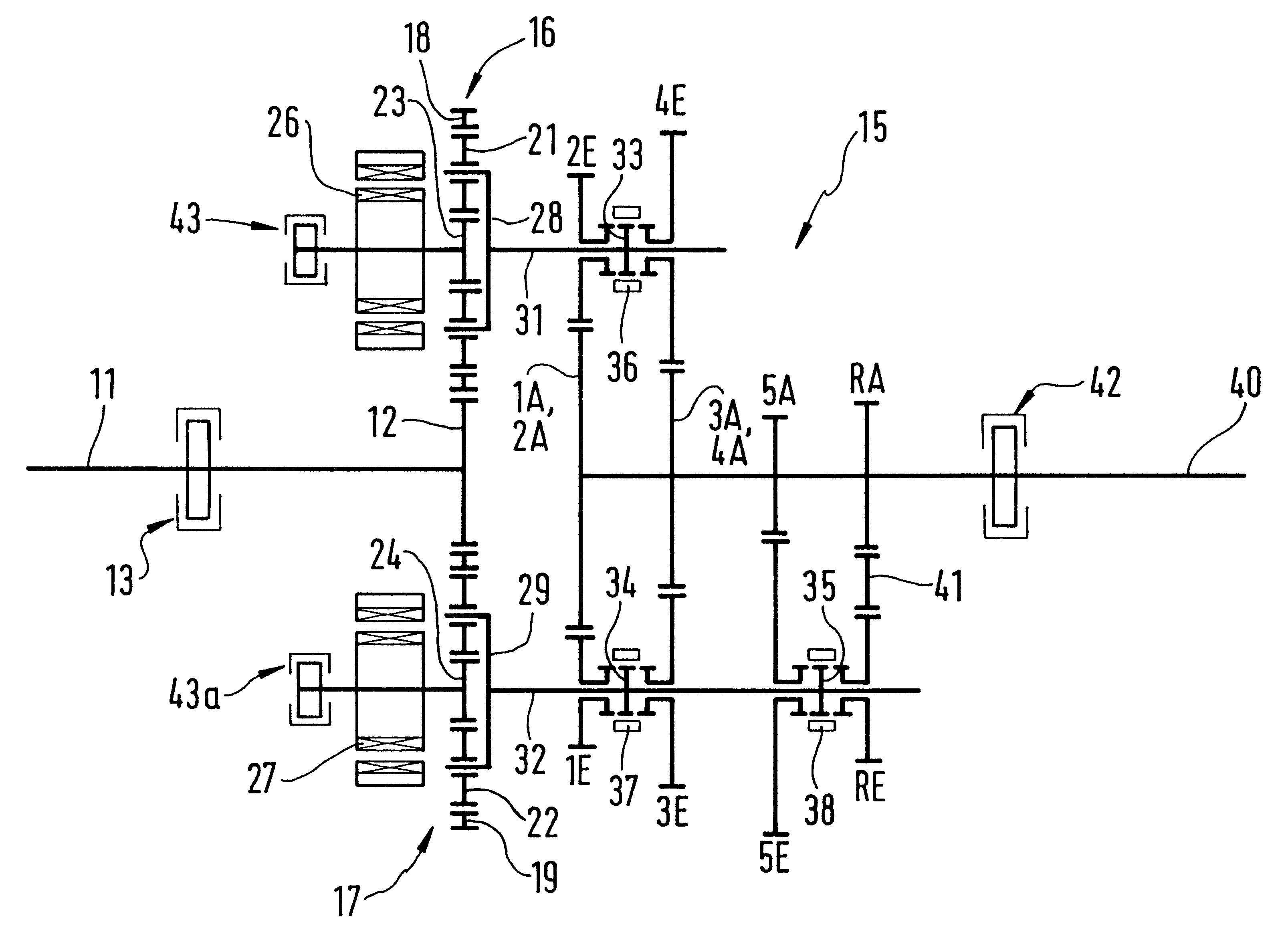
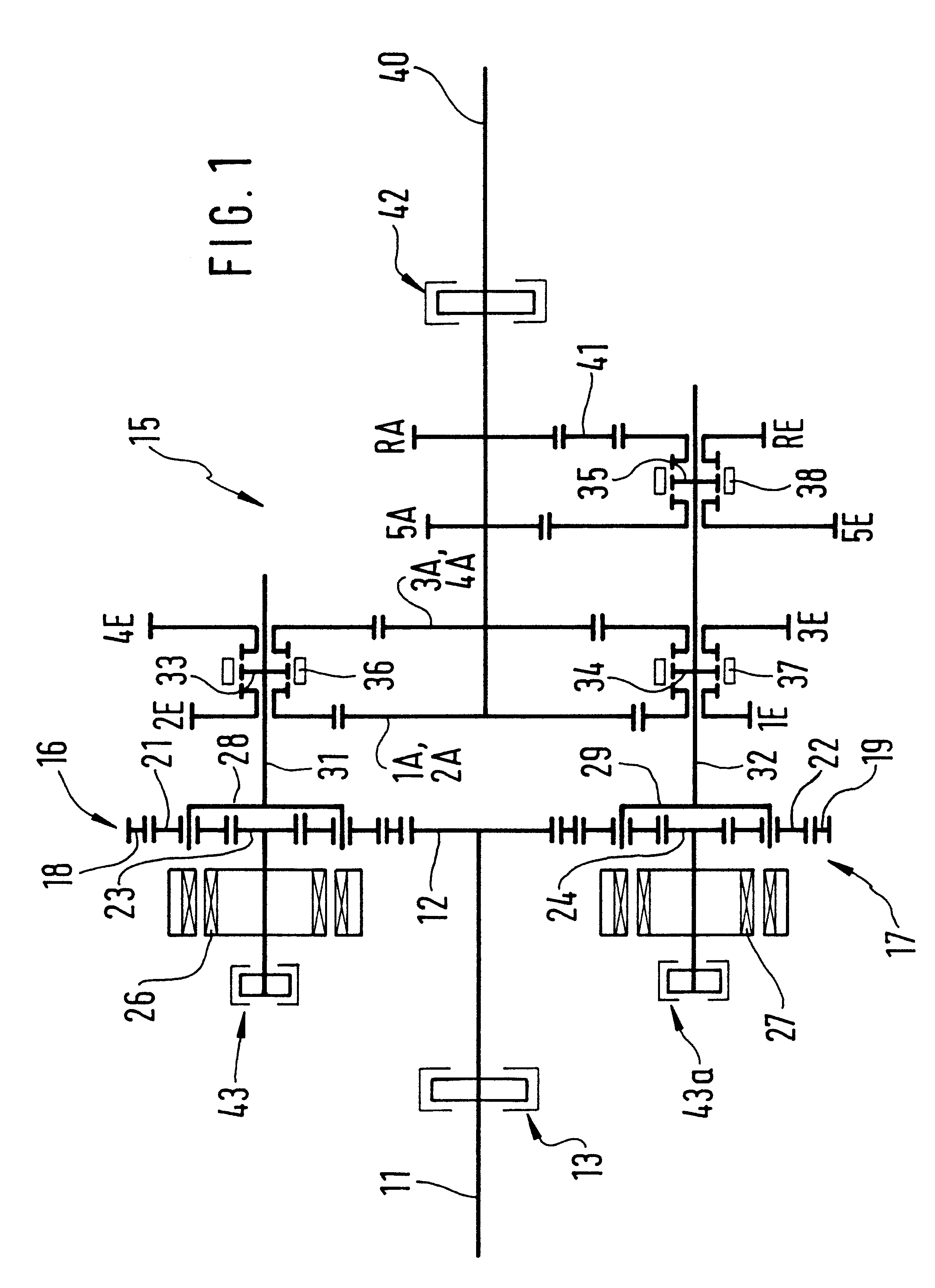
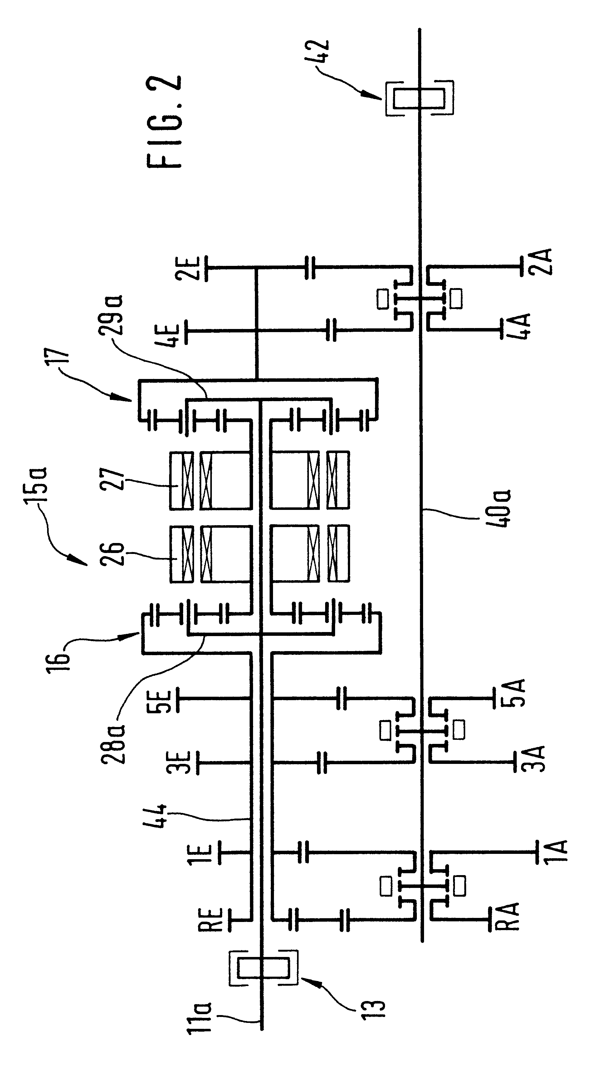
In FIG. 1, part of the drive train of a motor vehicle is shown. Among other parts, the drive train includes the crankshaft 11 of an internal combustion engine, not otherwise shown, at the end of which a crown gear 12 is provided. The crankshaft 11 also cooperates with an engine brake 13. A transmission 15, which in the exemplary embodiment is embodied as a three-shaft transmission, can be coupled to the crown gear 12.

The transmission 15 has two preferably identical planetary trains, in particular two planetary gear sets 16, 17. Each planetary gear set 16, 17, in a manner known per se, has a respective ring gear 18, 19 with teeth on the inside and outside, a plurality of planet wheels 21, 22, and one sun wheel 23, 24. The coupling of the transmission 15 to the crown gear 12 is effected via the sets of external teeth of the ring gears 18, 19 of the planetary gear sets 16, 17. On the side of the planetary gear sets 16, 17 toward the crankshaft 11, each sun wheel 23, 24 is coupled to on...


PUM


Abstract

A transmission (15; 15a; 15b; 15c), in particular for motor vehicles, has two planetary gears (16; 16c, 17; 17c), whose ring gears (18; 18c, 19) are connected by a crown gear (12) to the crankshaft (11; 11a; 11c) of an internal combustion engine. Each planetary gear (16; 16c, 17) is coupled to a respective gear shaft (31, 32), on which input gear wheels (1E-5E, RE) for various gear ratios are disposed. The input gear wheels (1E-5E, RE) mesh with output gear wheels (1A-5A, RA) disposed on an output shaft (40; 40a; 40c). It is provided that each planetary gear (16; 16c, 17) be coupled with an electric machine (26, 27), and the electric machines are for instance connected to the sun wheels (23; 23a, 24; 24a) of the planetary gear (16; 16c, 17). With the arrangement described, especially for use in hybrid vehicles, relatively high total efficiency and infinitely variable gear ratios can be achieved.

Description

PRIOR ARTThe invention relates to a transmission, in particular for motor vehicles, as generically defined by the preamble to claim 1. One such transmission is described in the article entitled "A development of Toyota Hybrid System" (Technical Review, Vol. 47, No. 2, Apr. 2, 1998). In the known transmission for a hybrid vehicle, a single planetary gear is provided. Its ring gear connected to the output shaft is coupled to a first electric machine, while the sun wheel is connected to a second electric machine. Via the planet carrier connected to the drive shaft or crankshaft of the internal combustion engine, a driving moment is introduced into the planetary gear. By varying the rotary speed of the sun wheel coupled to the second electric machine, an arbitrary rotary speed can be established for a given planet wheel rotation, generated by the engine, at the ring gear, and as a result arbitrary gear ratios between the ring gear and thus the output shaft and the engine can be attained...

Claims


Application Information

Patent Timeline
IPC IPC(8): B60K6/00B60K6/04B60K1/02B60K1/00F16H3/72F16H3/44B60K6/36B60K6/365B60K6/445B60K6/547B60W10/26
CPCF16H37/0826B60K6/365B60K6/445B60K6/547B60W10/26B60K6/36B60K1/02B60W10/103B60W10/113F16H3/006F16H3/725F16H3/728F16H37/0813F16H2200/0047Y10S903/909Y10S903/91Y10S903/919Y02T10/6239F16H2061/0422F16H2061/0444Y02T10/62
Inventor SCHNELLE, KLAUS-PETER
Owner ROBERT BOSCH GMBH
Why Eureka
Try Eureka