DC compensation system for a wireless communication device configured in a zero intermediate frequency architecture

a wireless communication and compensation system technology, applied in the direction of amplitude demodulation, gain control, digital transmission, etc., can solve the problems of limited location of each device, many limitations, and a significant problem in cable managemen

Inactive Publication Date: 2003-05-06
M RED INC
View PDF8 Cites 182 Cited by
  • Summary
  • Abstract
  • Description
  • Claims
  • Application Information

AI Technical Summary

Benefits of technology

It is appreciated that removal of the IF portion of a high performance wireless transceiver, with proper DC compensation, results in a relatively high performance, low cost wireless ZIF transceiver with reduced power requirements. The use of a DC compensation loop interfaced to the gain loop according to embodiments of the present invention achieves these goals. Such capability enables a WLAN system to be designed for use at home or in the small business that is relatively robust and that has significant performance with relatively high data throughput operation.

Problems solved by technology

Wired networks provide a certain level of convenience but have many limitations.
The location of each device, therefore, is limited to enable access to the network wires.
Cable management is also a significant issue, since devices must be placed to enable proper routing of wires.
Once wired devices are properly placed, movement of the devices is very limited or otherwise not practical without substantial re-configuration or re-routing of the wires.
Maintenance of wired network devices can be inconvenient and often requires that the wires be removed during service and then reconnected properly.
For network applications, infrared technology is a relatively inexpensive option but has certain limitations, including limited bandwidth, range limitations, and line-of-sight issues.
Due to line of sight issues, infrared technology is not particularly convenient for network communications at the end points of the network where human interaction is necessary.
RF technology for LAN systems, however, is not particularly optimized for small office or home use.
The wireless embodiments for commercial and industrial applications are too expensive or otherwise specialized and thus are not suited for direct use in the small office or home environment.
The Bluetooth technology, however, has limited bandwidth and therefore relatively low data throughput capability.
The typical environment for a WLAN is very noisy and not optimal for wireless communications.
For example, most homes include many electronic devices resulting in an electronically noisy environment that may interfere with WLAN communications, such as microwave ovens, garage door openers, radios, television sets, computer systems, etc.
Further, the communication medium between wireless devices constantly changes.
For example, most environments or rooms include multiple reflective surfaces creating multipath noise in the wireless environment.
Furthermore, movement of items or devices or the like such as hands, bodies, jewelry, mouse pointers, etc. or activation of electronic devices, such as cooling fans or the like, affects the overall wireless communication path and potentially degrades wireless communication performance.

Method used


Image

  • DC compensation system for a wireless communication device configured in a zero intermediate frequency architecture
  • DC compensation system for a wireless communication device configured in a zero intermediate frequency architecture
  • DC compensation system for a wireless communication device configured in a zero intermediate frequency architecture

Examples


Embodiment Construction

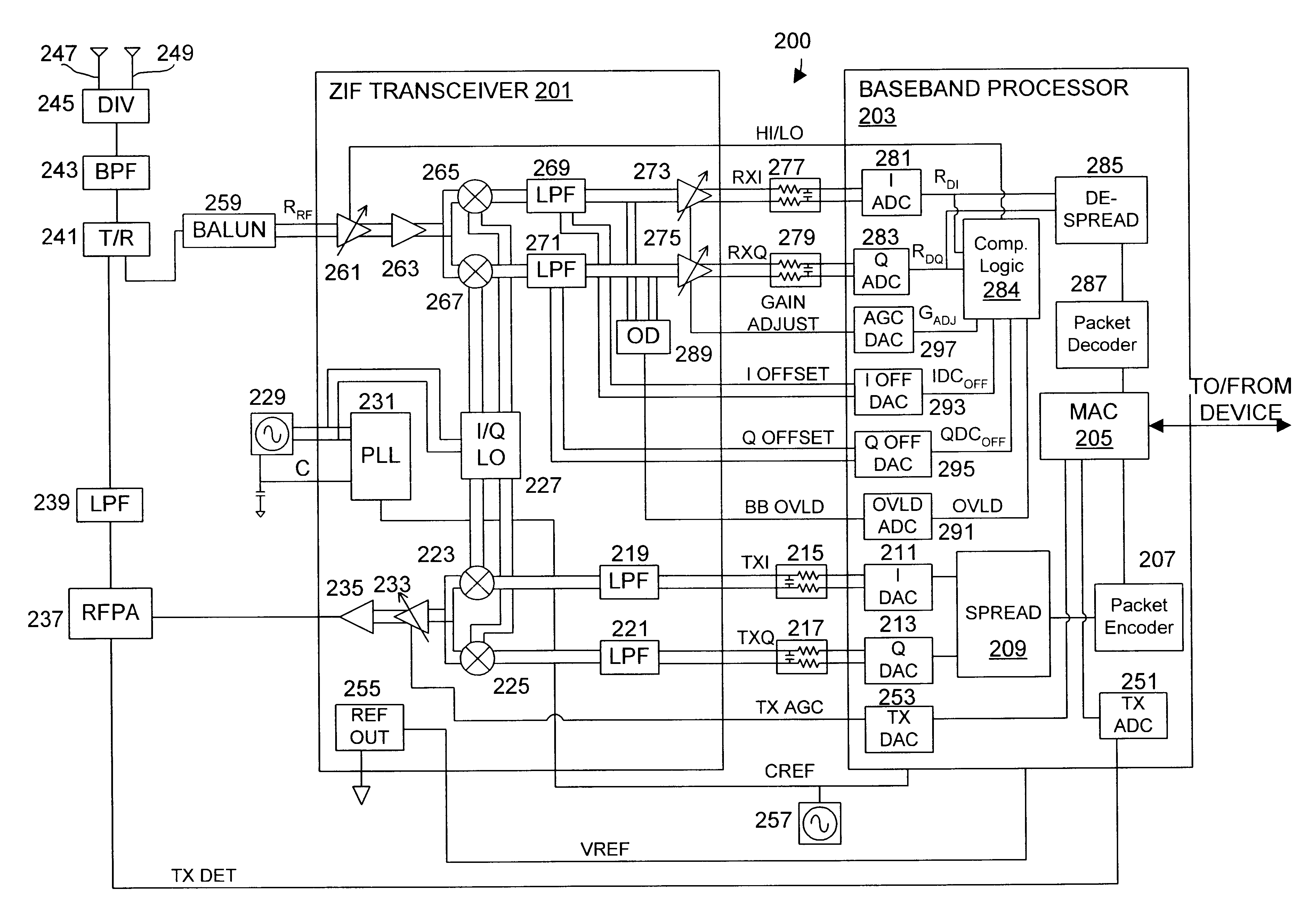
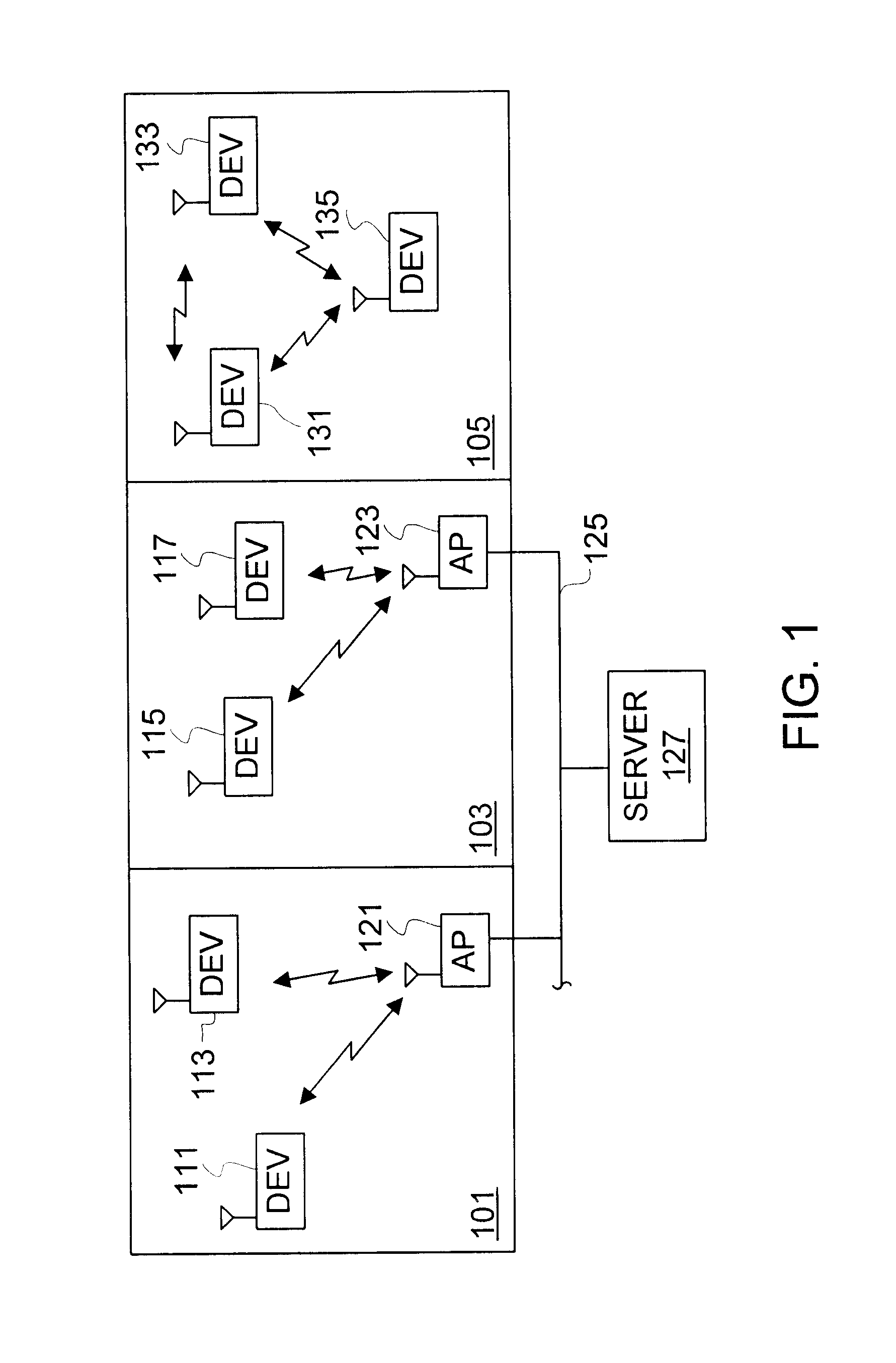
FIG. 1 is a block diagram of one or more WLANs generally illustrating operation of wireless devices implemented according to one or more embodiments of the present invention. Although the present invention is illustrated for use with WLANs in exemplary embodiments, it is understood that the present invention applies for any radio or wireless communications and is not limited to WLAN applications. A first area 101 and a second area 103 represent separate compartments or divisions of a location such as offices within an office building or rooms within a house. The areas 101 and 103 may each include wireless access points (APs) 121 and 123 for controlling communications within the respective areas 101 and 103. As shown, the APs 121, 123 are coupled to a wired network such as a LAN 125, which is further coupled to a common server computer 127.

Within the area 101, wireless devices 111 and 113 are able to communicate with each other via the AP 121, and within the area 103, wireless device...


PUM


Abstract

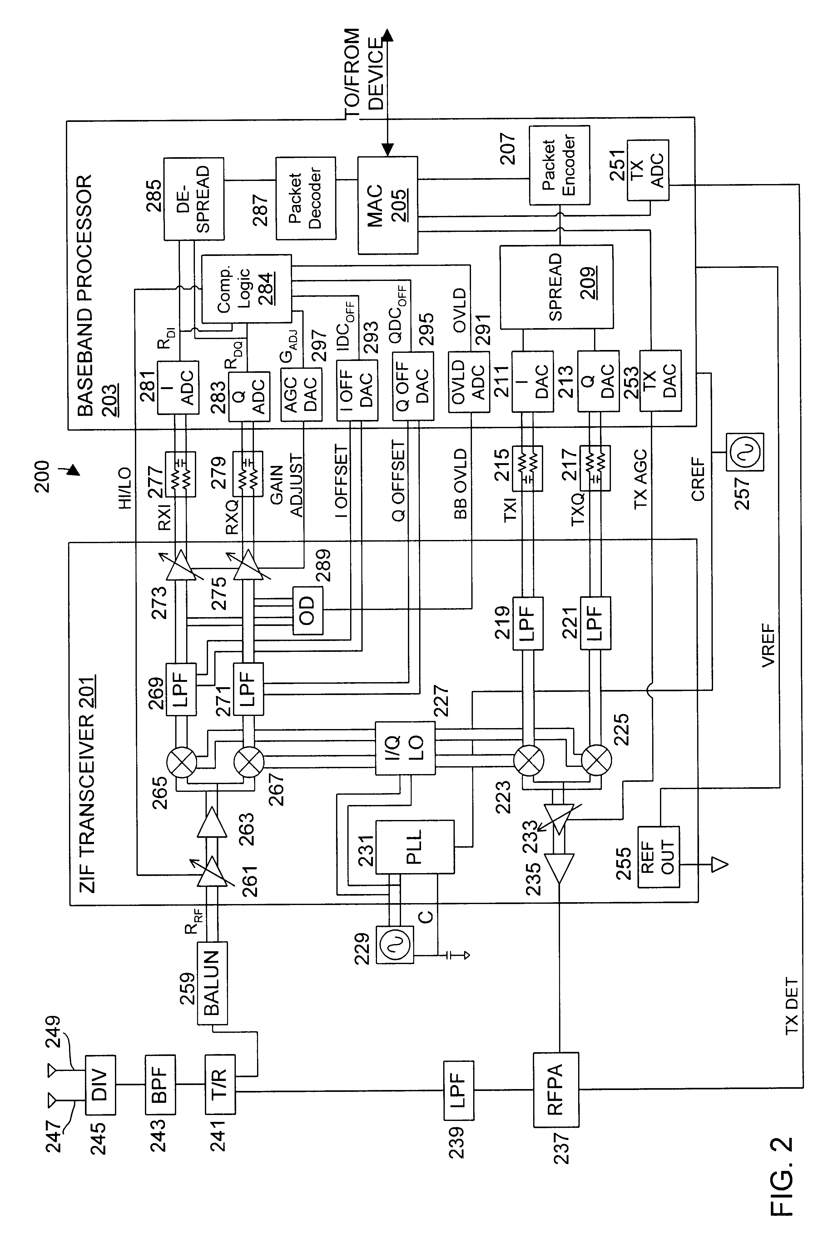
A wireless communication device including a radio frequency (RF) circuit, a ZIF transceiver and a baseband processor. The ZIF transceiver includes an RF mixer circuit that converts the RF signal to a baseband input signal, a summing junction that subtracts a DC offset from the baseband input signal to provide an adjusted baseband input signal, and a baseband amplifier that receives the adjusted baseband input signal and that asserts an amplified input signal based on a gain adjust signal. The baseband processor includes gain control logic, DC control logic and a gain interface. The gain control logic receives the amplified input signal, estimates input signal power and asserts the gain adjust signal in an attempt to keep the input signal power at a target power level. The DC control logic estimates an amount of DC in the amplified input signal and provides the DC offset in an attempt to reduce DC in the amplified input signal. The gain interface converts gain levels between the gain control logic and the DC control logic. The RF signal may include in-phase (I) and quadrature (Q) portions, where the RF mixer circuit splits I and Q baseband input signals from the RF signal. Operation is substantially identical for both I and Q channels. The DC control logic operates to remove or otherwise eliminate DC from the received signal that is provided to decoders in the baseband processor.

Description

The present invention relates to wireless communications, and more particularly to a DC compensation system for a wireless communication device configured in a zero intermediate frequency (ZIF) architecture that utilizes a DC control loop to enable direct conversion of radio frequency signals to baseband frequency.DESCRIPTION OF RELATED ARTNetwork communication is a growing area of technology both for business and home applications. A network system enhances communication and provides a suitable environment for enhanced productivity and capabilities both at home and in the workplace. The Internet for example, is a global, mostly wired, communication network that couples devices together on a world-wide basis that enables world-wide communication between any devices coupled to the Internet. The Internet enables access to a plurality of services, such as file sharing, faxing, chat, email and information access via websites to files, libraries, databases, computer programs, etc.Many bu...

Claims


Application Information

Patent Timeline
Patent Type & Authority Patents(United States)
IPC IPC(8): H04B1/30H03D3/00H03G3/20H03G3/30H04B1/16
CPCH04B1/30H03D3/008
Inventor BALDWIN, KEITH R.LANDY, PATRICK J.WEBSTER, MARK A.SCHULTZ, R. DOUGLASPRENTICE, JOHN S.
Owner M RED INC
Why Eureka
Try Eureka