Exhaust gas purification apparatus of internal combustion engine

a technology of exhaust gas purification apparatus and internal combustion engine, which is applied in the direction of machines/engines, electrical control, separation processes, etc., can solve the problems of unstable fuel combustion state, exhaust emission worsening, and three-way catalysts not being able to purify exhaust gas sufficiently

Inactive Publication Date: 2003-05-13
DENSO CORP
View PDF28 Cites 32 Cited by
  • Summary
  • Abstract
  • Description
  • Claims
  • Application Information

AI Technical Summary

Benefits of technology

In order to achieve the object, in order to remove HC (HC) released from a HC absorbent within a catalyst for absorbing HC due to a rising temperature of the substance, an exhaust gas purification apparatus according to a first aspect of the present invention is provided with a catalyst-early-warming means for early raising the temperature of the catalyst right after the internal combustion engine start to activate the catalyst at an early time. Since the catalyst can be activated with certainty right after the internal combustion engine start before the amount of HC absorbed by the HC absorbent reaches a saturation level, the HC absorbent is capable of absorbing unburned HC reliably right after the engine start, thereby allowing the exhaust gas to be cleaned by the catalyst. Therefore, the amount of HC exhausted right after the engine start can be considerably reduced in comparison with the conventional catalyst. In addition, the time for activation of the catalyst can be made shorter. Thus, the amount of HC absorbed by the HC absorbent can be reduced by a quantity proportional the decrease in time. As a result, it is possible to satisfy the demand for a low cost and space saving without the need to increase the size of the HC absorbent.
By employing the two-layer coat catalyst, the catalyst in the upper layer directly exposed to exhaust gas is heated first to an activation temperature before the HC absorbent in the lower layer is heated to an releasing temperature so that the catalyst in the upper layer is capable of removing HC released from the HC absorbent with certainty. In addition, by providing the two-layer coat catalyst at a location in close to the exhaust manifold, the catalyst can be exposed to high temperature exhaust gas. Thus, the catalyst can be activated in an even shorter period of time by the high-temperature exhaust gas in conjunction with a catalyst early-warming effect provided by the catalyst-early-warming means. As a result, the effect of reducing the amount of HC exhausted at the internal combustion engine start can be further increased.
A second object of the present invention is to provide an early-warming control apparatus that is capable of warming a catalyst for purifying exhaust gas at an early time by generating after-burning inside a path through which the exhaust gas flows without an ignition device in the path, and offers a simplified configuration and a reduced cost as well as an improved catalyst-warming function.
In order to achieve the object, in an early-warming control apparatus for warming a catalyst for purifying exhaust gas of an internal combustion engine at an early time in accordance with a second aspect of the present invention, in execution of control to heat a catalyst at an early time, an exhaust-gas-heating control means executes ignition retard control to raise the exhaust gas temperature making a rich component of the exhaust gas burnable inside the path, and a cylinder deactivation operation control means halts injection of fuel into some cylinders of the internal combustion engine, operating the internal combustion engine by using the remaining cylinders. A cylinder, injection of fuel to which is halted, is referred to as a halted-injection cylinder and the remaining cylinders are each known as a working cylinder. By doing so, in execution of the control to heat a catalyst at an early time, gas exhausted by the working cylinder is heated to the temperature making the exhausted gas burnable inside the path due to the ignition retard control. Thus, when rich components such as HG and CO of this high-temperature exhaust gas are mixed with oxygen of unburned air exhausted by the halted-injection cylinder, after-burning occurs in the path and the temperature of the catalyst is raised by combustion heat generated by the after-burning. As a result, the catalyst can be heated at an early time after the engine start and, since there is no need to install an ignition device for igniting exhaust gas, the configuration can be made simple and the cost can be reduced.

Problems solved by technology

Thus, the three-way catalyst is not capable of purifying the exhaust gas sufficiently.
As a result, the exhaust emission is worsened.
In the cold state of the internal combustion engine right after the engine start, the state of fuel combustion is unstable, generating a considerably large amount of unburned HC.
Thus, when it takes a long time to activate the three-way catalyst or the two-layer coat catalyst, the amount of HC absorbed by the two-layer coat catalyst becomes saturated, thereby making it no longer possible for the catalyst to absorb HC.
As a result, the amount of HC exhausted to the atmosphere increases.
However, not only does this solution dissatisfy a demand for a low cost and space saving, but it also takes an even longer time to raise the temperature of the two-layer coat catalyst or to activate the two-layer coat catalyst.
In particular, in a configuration wherein the two-layer coat catalyst is installed at the downstream side of the three-way catalyst as in the disclosed case, since the distance from the engine to the two-layer coat catalyst is large, the gas loses heat before the time when the exhaust gas enters into the catalyst, thereby inevitably decreasing the temperature thereof.
Thus, it unavoidably takes too long time to increase the temperature of the two-layer coat catalyst or to activate the catalyst.
As a result, the HC absorbing layer is no longer capable of absorbing HC.
Thus, the proposed technique has problems of complicated configuration and high cost.
As a result, it is feared that HG released from the HG absorbent cannot be removed by using the catalyst and is exhausted to the atmosphere.

Method used


Image

  • Exhaust gas purification apparatus of internal combustion engine
  • Exhaust gas purification apparatus of internal combustion engine
  • Exhaust gas purification apparatus of internal combustion engine

Examples


first embodiment

(First Embodiment)

The first embodiment of the present invention is explained by referring to FIGS. 1 and 2 as follows.

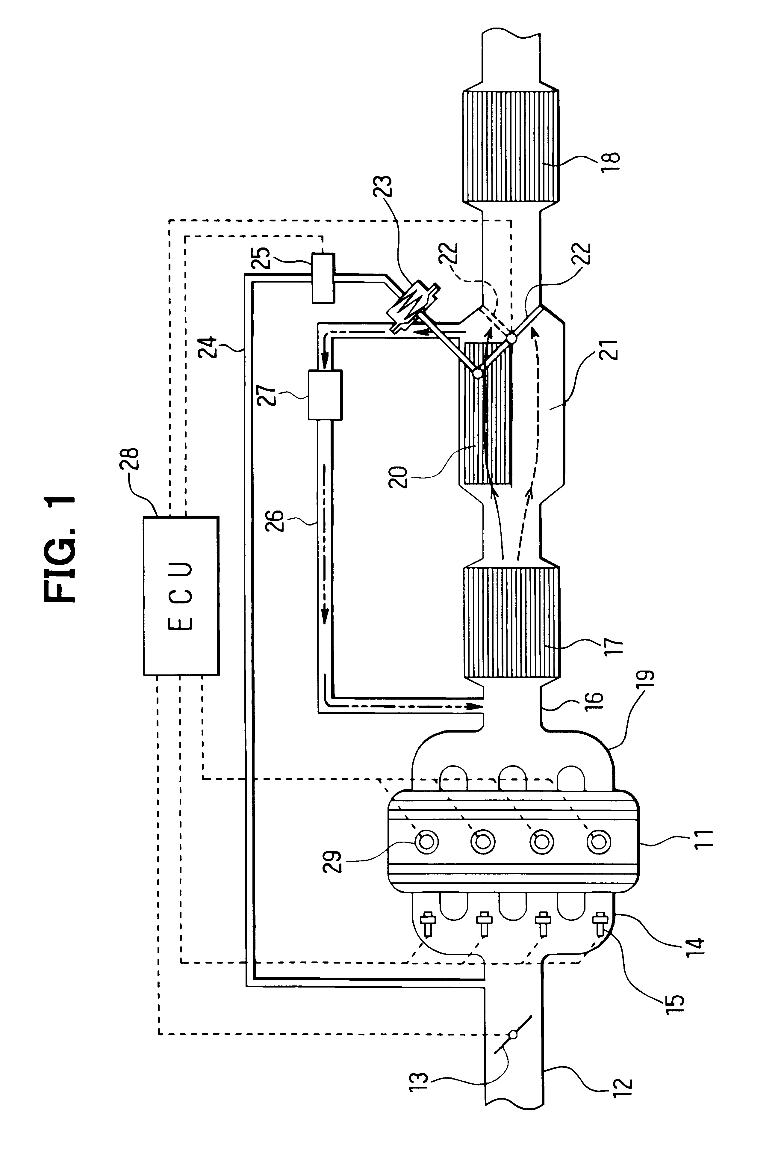
As shown in FIG. 1, a throttle valve 13 for adjusting throttle opening is provided in an intake pipe 12 of an engine 11. A fuel injection valve 15 for injecting fuel into cylinders is provided in cylinder branch pipe units of an intake manifold 14 for introducing fuel into the cylinders.

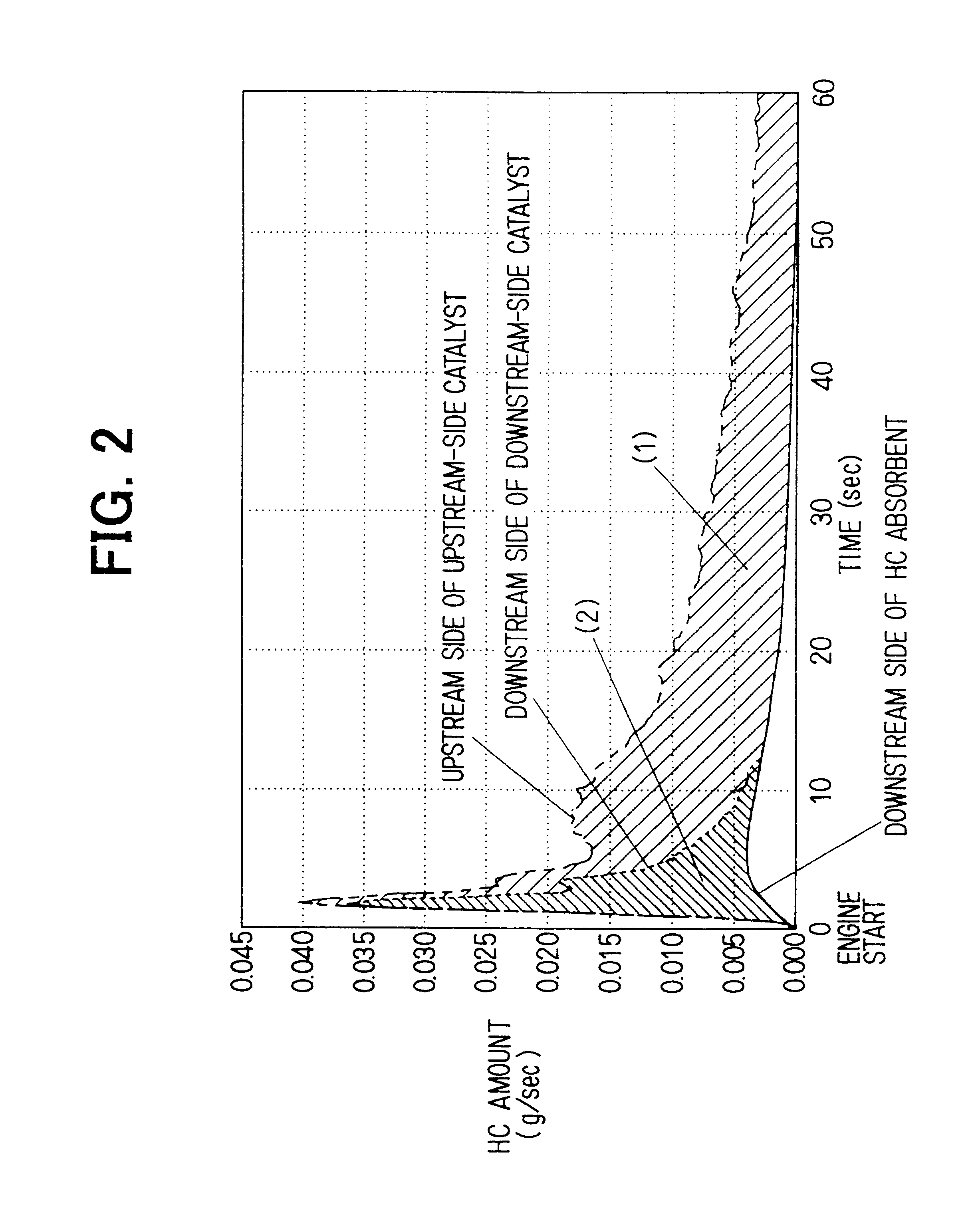
An upstream-side catalyst 17 and a downstream-side catalyst 18, which are used for reducing the quantity of each noxious component in exhaust gas, are provided in series on an exhaust pipe 16 of the engine 11. The upstream-side and downstream-side catalysts 17 and 18 are each a three-way catalyst for removing HC, Co and NOx or an oxide catalyst for removing HC and CO. The upstream-side catalyst 17 is provided at a location close to an exhaust manifold 19, so that early activation thereof can be completed while the engine 11 starts. The downstream-side catalyst 18 is provided typically...

second embodiment

(Second Embodiment)

The second embodiment of the present invention is explained with reference to FIGS. 3-7. In the second embodiment, a two-layer coat catalyst 30 is provided at a location close to the exhaust manifold 19 in the exhaust pipe 16 as shown in FIG. 3. A downstream-side catalyst 18 is provided at the downstream side of the two-layer coat catalyst 30 typically on the lower surface of the vehicle body. As shown in FIG. 4, the 2-layer coat catalyst 30 is formed by coating an HC absorbent 32 made of typically zeolite on the inner surface of a catalyst support 31 and coating a catalyst 33 such as a three-way catalyst or an oxide catalyst on the surface of the HC absorbent 32. The catalyst support 31 has a shape resembling a honeycomb made of ceramic such as cordierite. The catalyst 33 is formed into a multi-porous shape having a large number of fine pores. The HC passes through the pores and flows to the HC absorbent 32 absorbing the HC.

The catalyst 33 in the two-layer coat c...

third embodiment

(Third Embodiment)

Next, the third embodiment of the present invention will be explained with reference FIGS. 8-12. As shown in FIG. 8, a throttle valve 63 for adjusting throttle opening is provided in an intake pipe 62 of an internal combustion engine 61. A fuel injection valve 65 for injecting fuel into cylinders is installed at a location in close to an intake port of an intake manifold 64 for introducing air to the cylinders. On the other hand, a catalyst 67 such as a three-way catalyst for removing HC, CO and NOx from exhaust gas is provided in an exhaust pipe 66 of the engine 61.

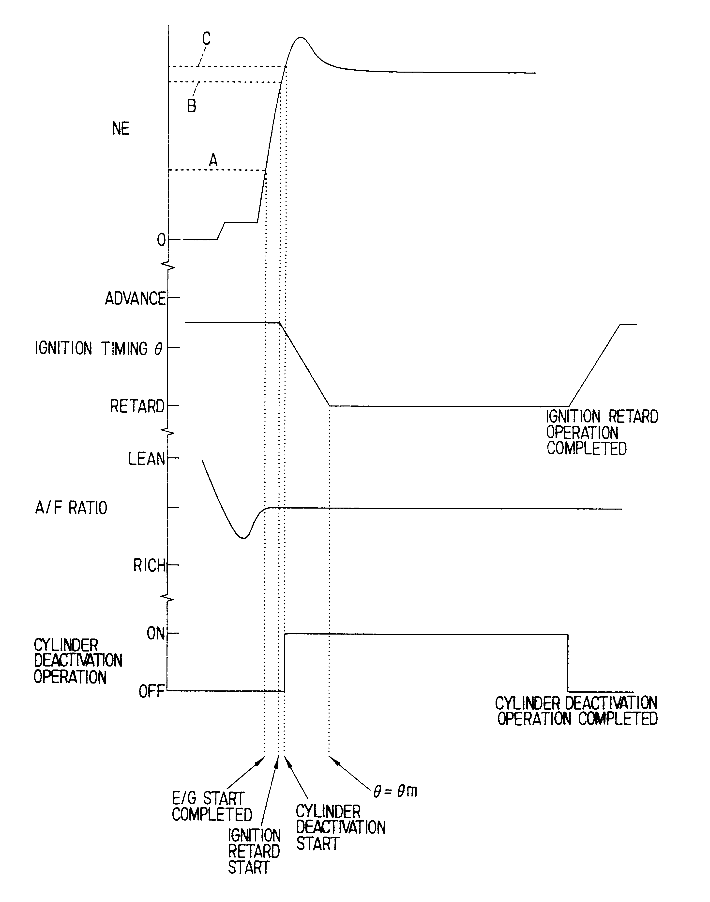
An engine control circuit 68, which is referred to hereafter as an ECU, employs a microcomputer as a main component. By execution of a fuel injection control program stored in an embedded ROM (a storage medium), the ECU 68 controls the quantity of the fuel injection of the fuel injection valve 65. In addition, by execution of an ignition control program stored in the ROM, the ECU 68 controls ignition ti...


PUM


Abstract

An upstream-side catalyst is provided at a location in close to an exhaust manifold of an engine. An HC absorbent and a downstream-side catalyst are installed in series at the downstream side. With the upstream-side catalyst put in an inactive state, the HC absorbent absorbs HC having passing through the upstream-side catalyst. After the upstream-side catalyst has been activated, HC released from the HC absorbent is refluxed to the upstream side of the upstream-side catalyst through a reflux path to be removed by the upstream-side catalyst. At that time, the ECU executes catalyst-early-warming control right after an engine start in order to raise the temperature of the upstream-side catalyst at an early time so as to shorten the time it takes to activate the upstream-side catalyst.

Description

This application is based on and incorporates herein by reference Japanese Patent Application Nos. Hei. 11-346386 filed on Dec. 6, 1999, and Hei. 11-365827 filed on Dec. 24, 1999.1. Field of the InventionThe present invention relates to an internal combustion engine exhaust gas purification apparatus for purifying exhaust gas from the internal combustion engine by removing HC from the exhaust gas.2. Description of Related ArtAn ordinary gasoline engine made in recent years has a three-way catalyst provided in an exhaust pipe thereof for purifying exhaust gas by removing noxious components of the exhaust gas such as HG, GO (carbon monoxide) and NOx (nitrogen oxide) from the gas. In the cold state of the internal combustion engine right after an engine start, however, the temperature of the three-way catalyst does not rise to an activation temperature. That is, the three-way catalyst is still in a non-activated state right after the engine start. Thus, the three-way catalyst is not ca...

Claims


Application Information

Patent Timeline
Patent Type & Authority Patents(United States)
IPC IPC(8): B01D53/94F01N3/08F02D41/02F01N3/20F02D41/36F02D41/32F01N7/00F01N7/02F01N13/02F02D41/00
CPCB01D53/944B01D53/9495F01N3/0814F01N3/0835F01N3/0871F01N3/0878F01N13/009F01N3/2006F02D41/0087F02D41/0255F01N13/0093F01N3/101Y02T10/26Y02T10/22Y02T10/12
Inventor KATSUTA, HIROYUKIMAJIMA, YOSHIHIROYAMASHITA, YUKIHIRO
Owner DENSO CORP
Why Eureka
Try Eureka