Current modulator with dynamic amplifier impedance compensation

Inactive Publication Date: 2003-05-20
ERICSSON INC
View PDF4 Cites 257 Cited by
  • Summary
  • Abstract
  • Description
  • Claims
  • Application Information

AI Technical Summary

Benefits of technology

The present invention provides a method and apparatus to dynamically compensate for changing power amplifier impedance in conjunction with providing amplitude modulated supply current to the power amplifier. This dynamic compensation is based on inferentially sensing changes in the DC resistance of the power amplifier arising from changes in power amplifier impedance associated with, for example, changes in transmit antenna coupling. Changes in power amplifier AM modulation

Problems solved by technology

Supply current modulation offers superior linearity but is not without its attendant challenges.
Such clipping causes potentially significant non-linearity resulting in a host of undesirable effect

Method used


Image

  • Current modulator with dynamic amplifier impedance compensation
  • Current modulator with dynamic amplifier impedance compensation
  • Current modulator with dynamic amplifier impedance compensation

Examples


Example

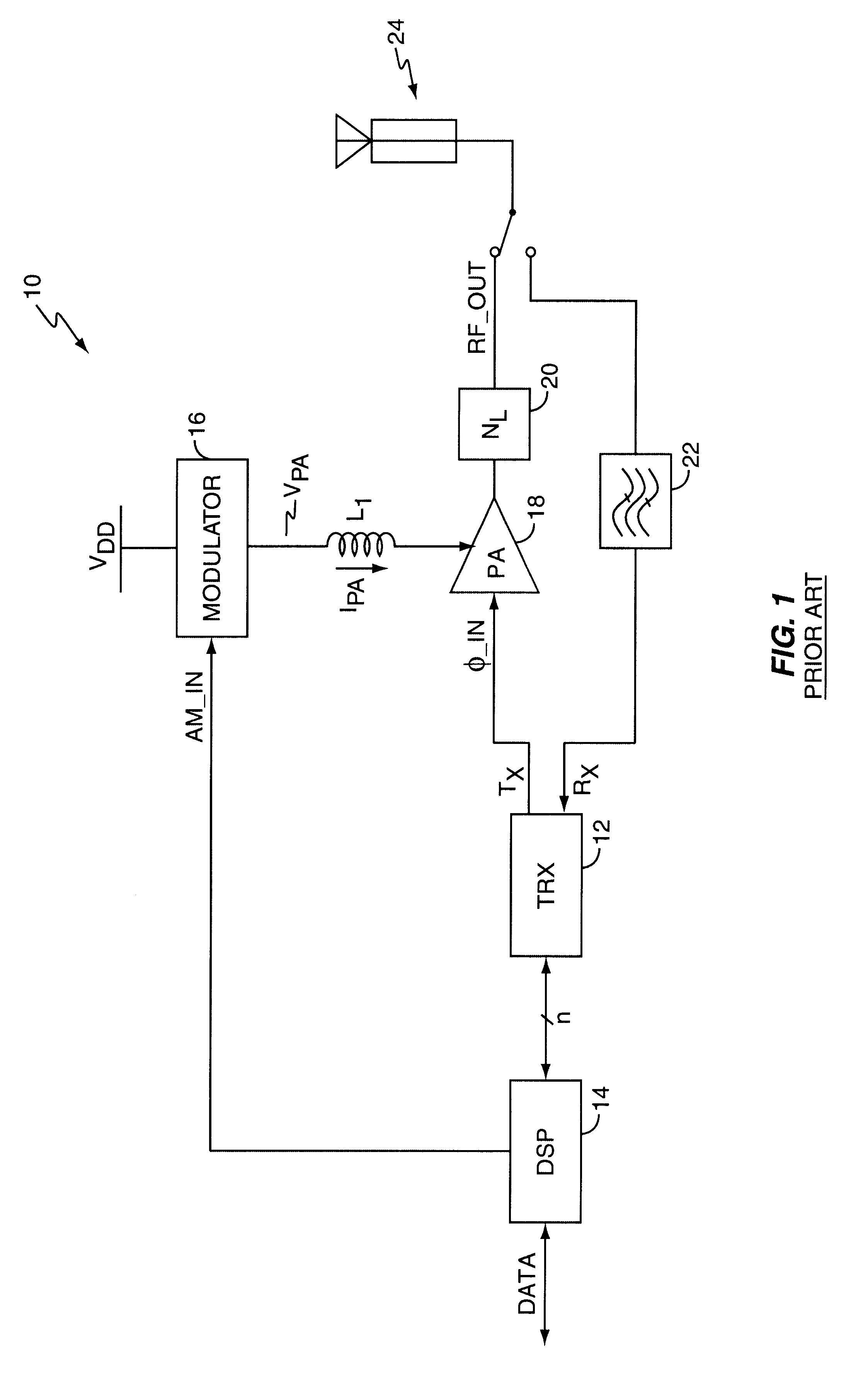
FIG. 1 illustrates a wireless communication device 10 employing a conventional current modulator. The device 10 comprises a transceiver 12, a digital signal processor (DSP) 14, a current modulator 22, and an antenna assembly 24. In operation, the transceiver 12 provides a constant envelope, phase modulated input signal to the power amplifier 18 based on desired transmit data received from the DSP 14. Additionally, the DSP 14 generates an amplitude modulation signal that drives modulator 16. In turn, modulator 16 generates a modulated supply current I.sub.PA, which serves as the input supply current to the power amplifier 18. The power amplifier 18 is operated in saturated mode such that the modulated supply current driven into the power amplifier output impedance generates amplitude modulations in the RF output signal from the power amplifier 18. Consequently, the RF output signal includes both phase and amplitude modulation information corresponding to the desired transmit data.

FIG...


PUM


Abstract

An amplitude modulation circuit (modulator) provides modulated supply current, possibly in combination with modulated supply voltage, to a radio frequency (RF) power amplifier (PA), and includes a detection circuit responsive to changes in the ratio of that voltage to the modulated supply current, described herein as its AM modulation impedance. Such impedance (resistance) changes commonly arise from changing coupling characteristics at the RF antenna assembly driven by the PA. A gain control circuit may be associated with the detection circuit, and made responsive thereto, thus allowing adjustment of modulation gain control responsive to changes in PA AM modulation impedance. In one embodiment, this arrangement permits the modulator to hold a fixed modulation gain over changing PA AM modulation impedance, while in other embodiments, modulation gain varies in response to PA impedance changes to avoid signal clipping. Such clipping might otherwise occur where current modulation values in combination with increased PA resistance would result in PA voltages exceeding the supply voltage of the PA.

Description

BACKGROUND OF THE INVENTIONThe present invention generally relates to power amplifier current modulation, and particularly relates to inferentially sensing changes in power amplifier resistance.Various techniques exist for generating radio frequency transmit signals used in wireless communication systems. These various approaches each entail advantages and disadvantages, but one consideration that is of significant importance with regard to mobile communication devices is the need for relatively good operating efficiency. Operating efficiency is generally a significant factor in the battery life of mobile communication devices. Power amplifier efficiency is a primary factor in overall operating efficiency because the power amplifier circuits used to generate radio frequency (RF) transmit signals are primary consumers of power in such devices.One technique used to gain power amplifier efficiency involves polar modulation where phase and amplitude modulation information representing d...

Claims


Application Information

Patent Timeline
IPC IPC(8): H03F1/02H03G3/00H03G3/30H03F3/24H03F1/06
CPCH03F1/0233H03F1/0272H03G3/3047H03G3/004H03G3/3042H03F2200/504H03F1/56H03F1/02
Inventor PEHLKE, DAVID R.HADJICHRISTOS, ARISTOTELECAMP, JR., WILLIAM O.
Owner ERICSSON INC
Why Eureka
Try Eureka