Bit face orientation control in drilling operations

Active Publication Date: 2007-11-08
VARCO I P INC
View PDF33 Cites 54 Cited by
  • Summary
  • Abstract
  • Description
  • Claims
  • Application Information

AI Technical Summary

Benefits of technology

[0011] The present invention discloses, in certain aspects, a system for accurately changing bit face orientation.
[0020] It is, therefore, an object of at least certain preferred embodiments of the present invention to provide new, useful, unique, efficient, nonobvious systems and methods, including, but not limited to, systems and methods for efficiently, accurately, and effectively orienting a bit in drilling operations, in certain aspects with a top drive system.

Problems solved by technology

One of the challenges for directional drilling is ensuring the directional motor is oriented properly for the desired change in drilling direction.
Certain current top drive control interfaces and software allow a driller to perform bit-face orientation movements with a top drive, but often these systems are inaccurate.
This is using the driller as a closed-loop position control portion of the operation, which can be undesirable.
For HMI-based human-machine interface top drives, the situation can be worse since the driller must key in a throttle on a touch screen, watch the movement of the drive, then quickly look back at the screen and hit “zero throttle” in order to stop the shaft.
This can lead to errors.
A driller maintains a desired face angle by applying torque or drillstring angle corrections to a drillstring, but because of the latency or delay in receiving face angle information, the driller often over- or under-corrects.
The over- or under-correction can result in substantial back and forth wandering of the drill bit, which increases the distance that must be drilled in order to reach the target formation.
Back and forth wandering can also increase the risk of stuck pipe and make the running and setting of casing more difficult.
However, due to the interference fit caused by such downhole deflection devices, significant contact forces are generated by such devices at the contact points (i.e., the bent knee and the intervening stabilizers).
As a result, not only is accuracy affected, but also the azimuth accuracy of the directional survey, since the survey data are influenced by the deformation of the downhole assembly.
Often the azimuth accuracy in an MWD survey, particularly near the horizontal section, can be very poor.
The uncertainty of the well trajectory, due to such azimuthal error, will either lead to strayed drilling or to a crooked horizontal well path.
This can limit the maximum drillable horizontal extent of the well.

Method used


Image

  • Bit face orientation control in drilling operations
  • Bit face orientation control in drilling operations
  • Bit face orientation control in drilling operations

Examples


Embodiment Construction

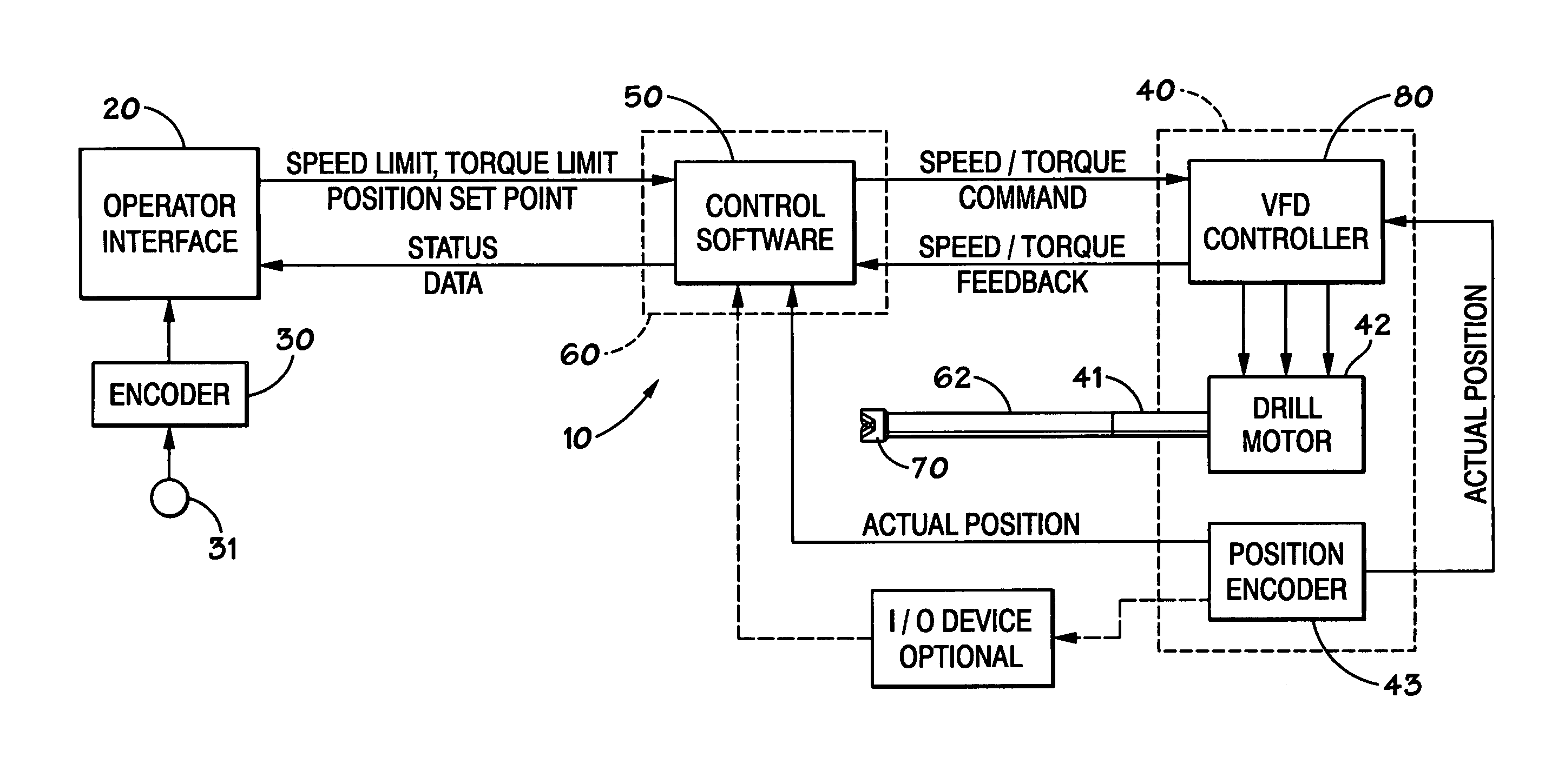
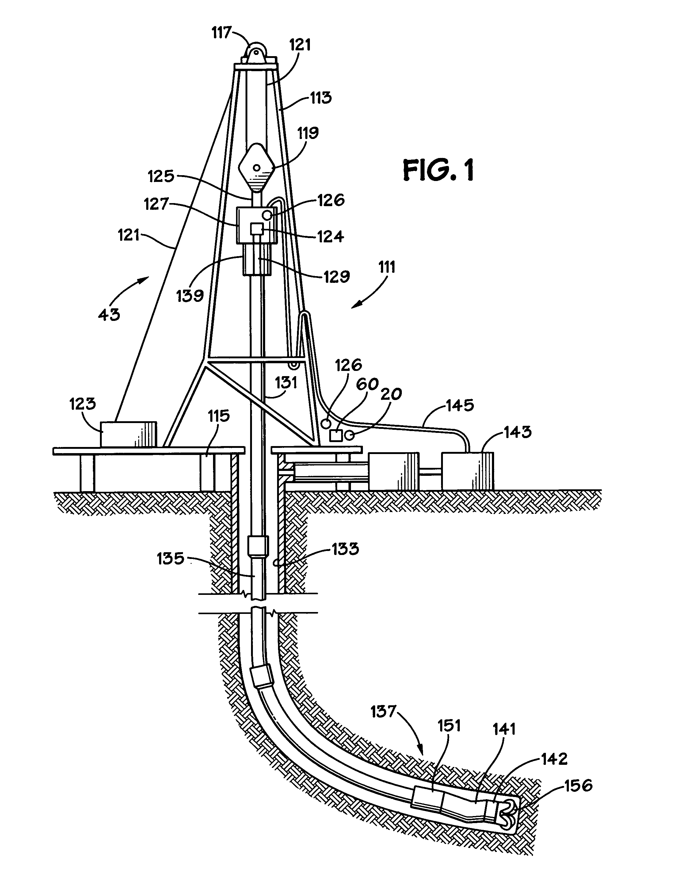
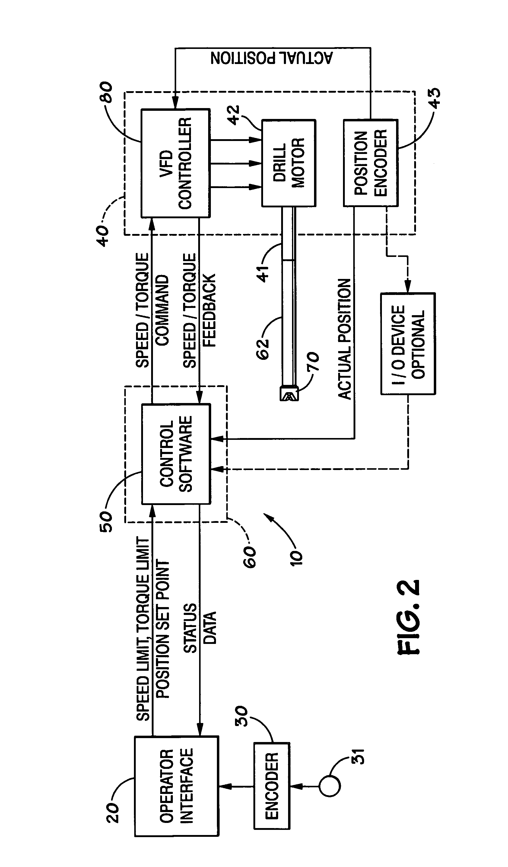
[0032] Referring now to FIG. 1, a drilling rig 111 is depicted schematically as a land rig, but other rigs (e.g., offshore rigs, jack-up rigs, semisubmersibles, drill ships, and the like) are within the scope of the present invention. In conjunction with an operator interface, e.g. an interface 20, a control system 60 as described below controls certain operations of the rig. The rig 111 includes a derrick 113 that is supported on the ground above a rig floor 115. The rig 111 includes lifting gear, which includes a crown block 117 mounted to derrick 113 and a traveling block 119. A crown block 117 and a traveling block 119 are interconnected by a cable 121 that is driven by drawworks 123 to control the upward and downward movement of the traveling block 119. Traveling block 119 carries a hook 125 from which is suspended a top drive system 127 which includes a variable frequency drive controller 126, a motor (or motors) 124 and a drive shaft 129. The top drive system 127 rotates a dr...


PUM


Abstract

A system for selectively orienting a bit at the end of a drillstring in a wellbore, the system, in certain aspects, having: motive apparatus for rotating a drillstring and a bit connected to an end of the drillstring; a control member manually movable to effect a change in orientation of the bit; a control system in communication with the motive apparatus and the control member for translating a signal from the control member indicative of manual movement of the control member into a command to the motive apparatus, the command commanding the motive apparatus to rotate the drillstring and the bit in correspondence to the movement of the control member.

Description

BACKGROUND OF THE INVENTION [0001] 1. Field Of The Invention [0002] This present invention is directed to drilling operations, systems for controlling the orientation of a drill bit during drilling, and, in certain particular aspects, to controlling bit face orientation during drilling. [0003] 2. Description of Related Art [0004] The prior art discloses a wide variety of drilling systems, apparatuses, and methods which use a rotary drive or top drive drilling system with a motor that rotates a drive shaft which in turn rotates a drillstring; including, but not limited to, the disclosures in U.S. Pat. Nos. 6,944,547; 6,918,453; 6,802,378; 6,050,348; 5,465,799; 4,995,465; 4,854,397; and 3,658,138, all incorporated fully herein for all purposes. One of the challenges for directional drilling is ensuring the directional motor is oriented properly for the desired change in drilling direction. This requires the top drive to move the string in order to move to specific positions rather tha...

Claims


Application Information

Patent Timeline
IPC IPC(8): E21B44/00
CPCE21B4/20E21B7/10E21B7/068E21B7/06
Inventor HULICK, KENT ERIN
Owner VARCO I P INC
Why Eureka
Try Eureka