
Hybrid expansible chamber engine with internal combustion and pneumatic modes

Inactive Publication Date: 2003-05-27
NANO PRECISION
View PDF14 Cites 32 Cited by
  • Summary
  • Abstract
  • Description
  • Claims
  • Application Information

AI Technical Summary

Benefits of technology

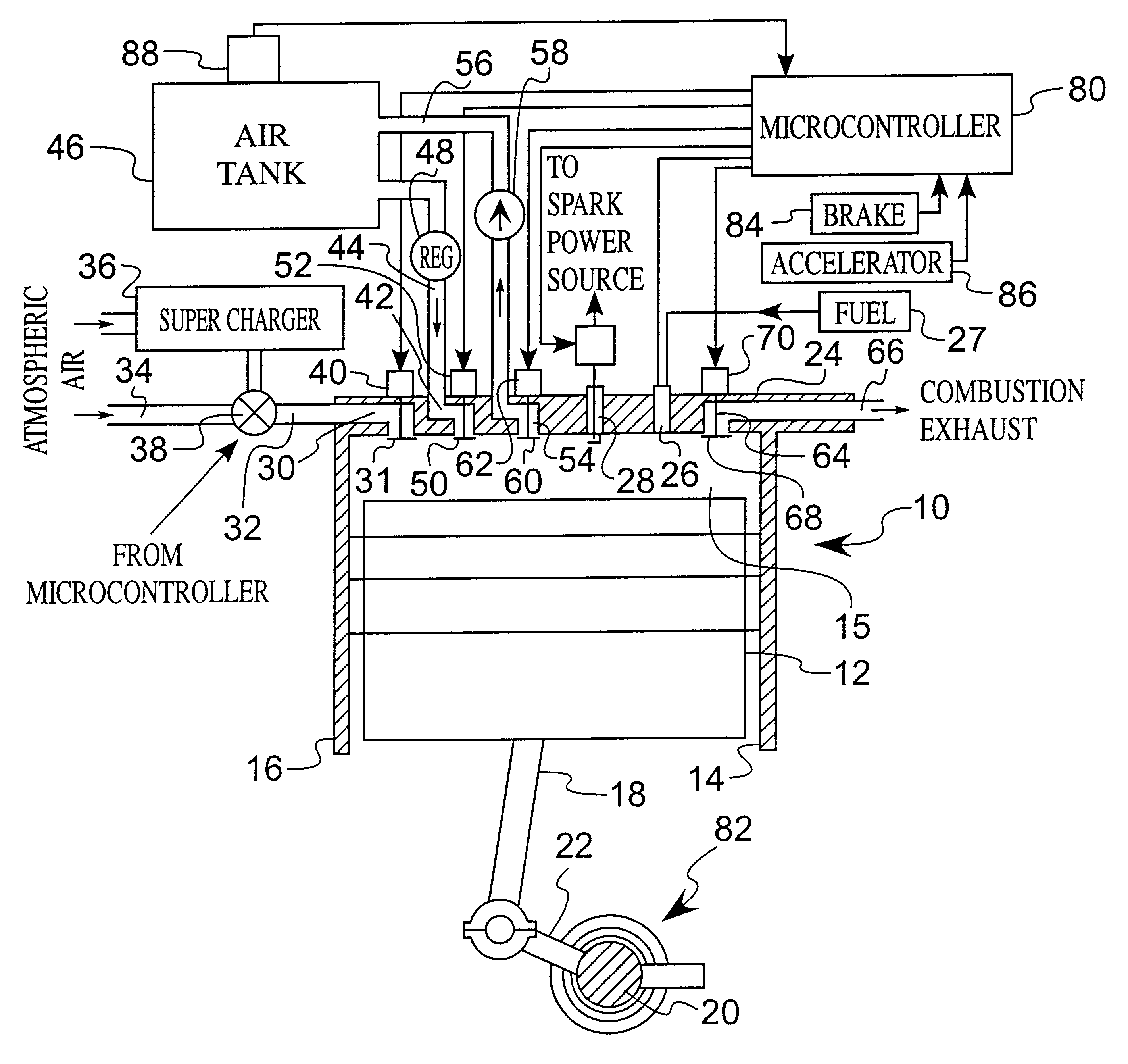
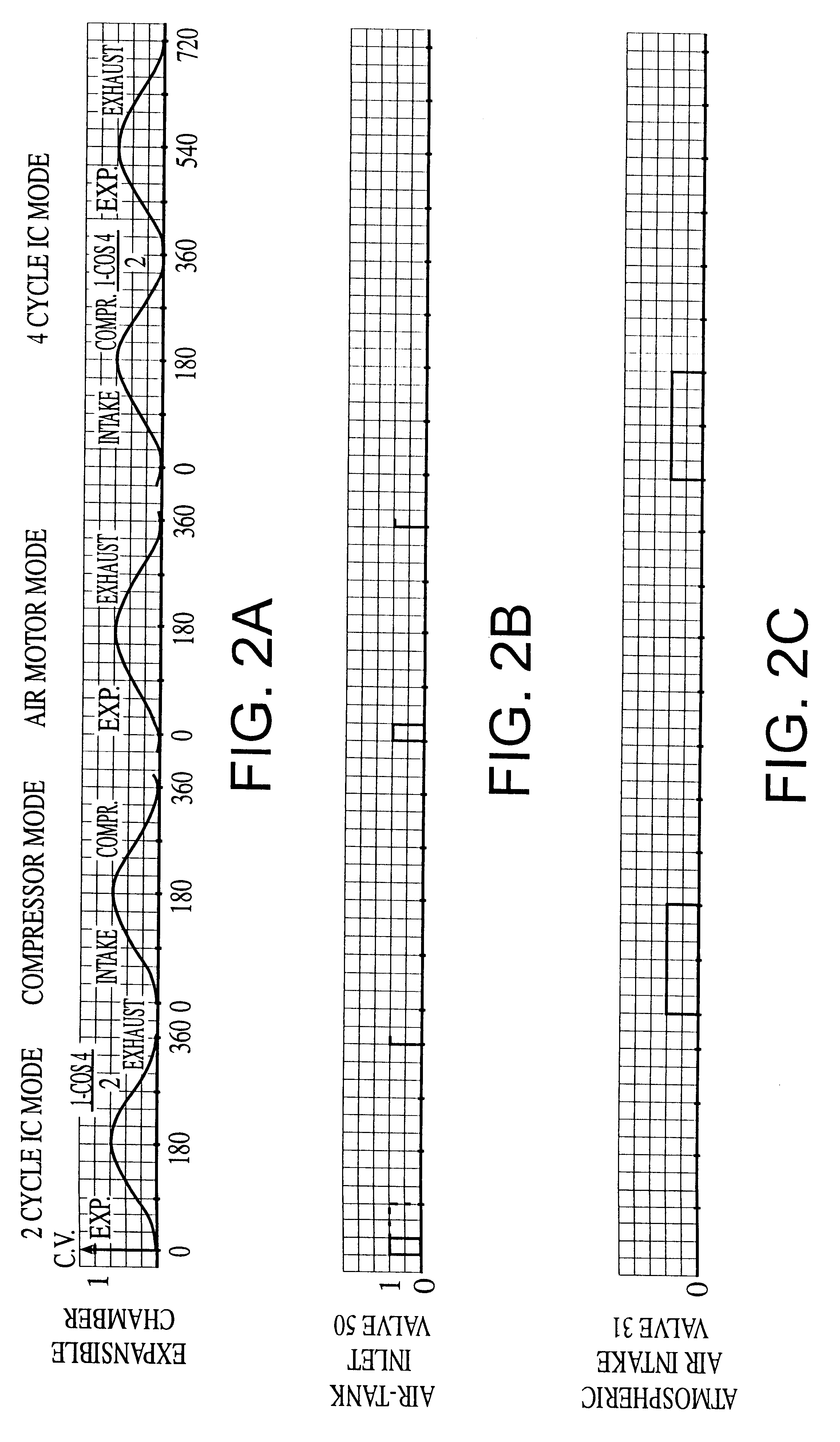
The invention is a hybrid expansible chamber engine, such as a piston and cylinder structure, having a plurality of expansible chamber devices coupled together. Each expansible chamber device is capable of operating in an internal combustion mode, an air motor mode and an air compressor mode. Consequently, the mode for each expansible chamber device can be switched among the available modes to accommodate current operating conditions, as those operating conditions change. This engine operates with known supporting devices such as an air storage tank for compressed air, a

Problems solved by technology

Although engines can be designed for very high fuel efficiency and low emission and engines can be designed for high performance and power, once an engine is constructed, the range of variations in these characteristics becomes substantially limited.
Although such hybrid IC-electric engines show substantial advantages and promise, they also suffer substantial disadvantages.
Electrically powered vehicles require batteries which add substantial weight to a vehicle, thereby reducing fuel efficiency.
Additionally, efficiency and fuel economy are deterred by the inefficiency of the process of converting energy from one form to another combined with the need for many such conversions with this type of hybrid engine.
Each energy conversion step has substantial energy loss and inefficiency inherent in the energy conversion processes.
In the hybrid IC-electric engine, the recovery of braking energy is limited by the current capacity of the motor / alternator / generator and also by the battery's maximum charging rate.
So far as is known, these engine concepts have not received significant commercial research and development, possibly because they, like the hybrid IC and electric engine, require the coupling of at least two separately identifiable engines which introduce the complications of coordinating and controlling their operation.

Method used


Image

  • Hybrid expansible chamber engine with internal combustion and pneumatic modes
  • Hybrid expansible chamber engine with internal combustion and pneumatic modes
  • Hybrid expansible chamber engine with internal combustion and pneumatic modes

Examples


Embodiment Construction

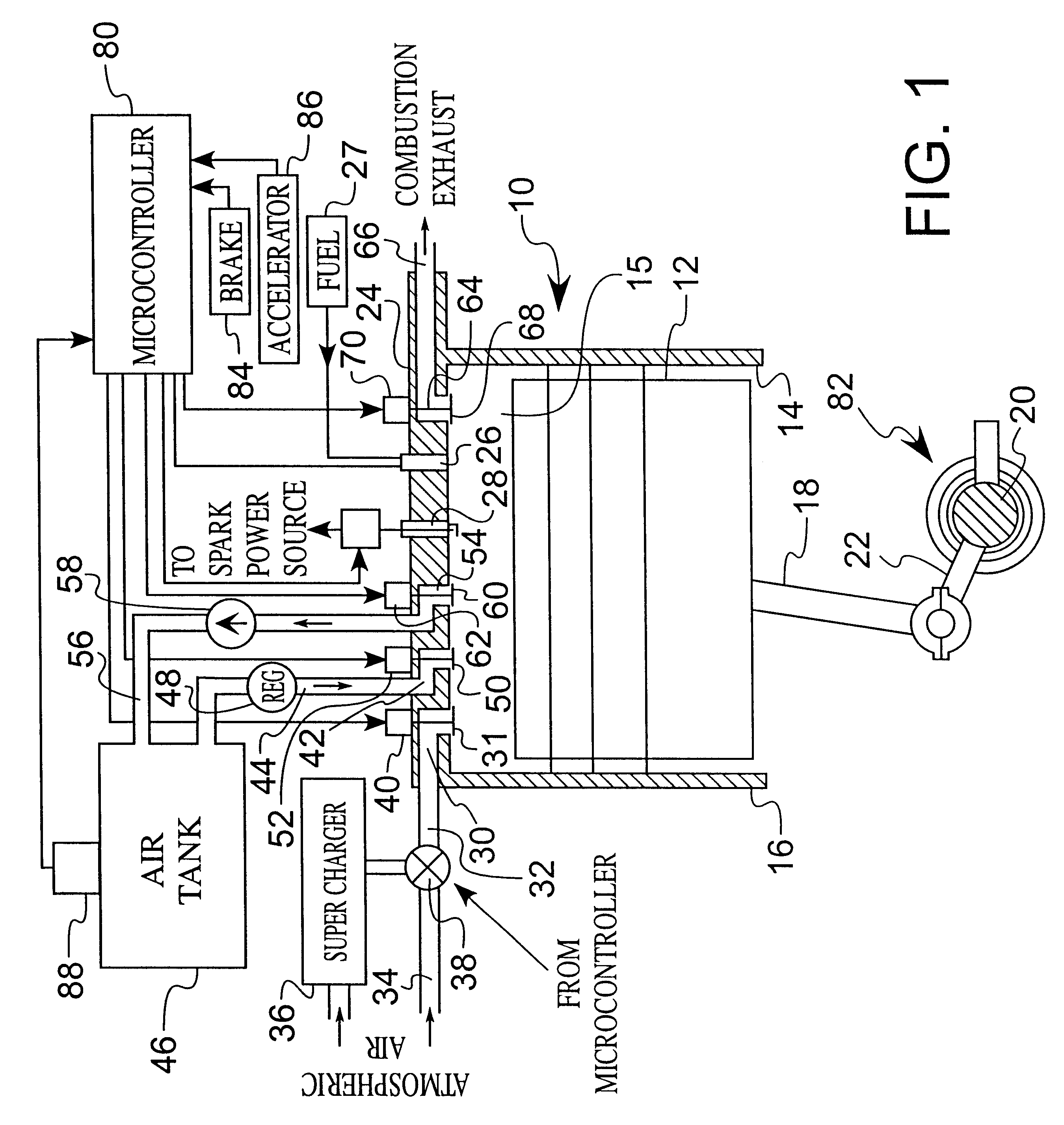
FIG. 1 illustrates an expansible chamber device 10 formed by a piston 12, which is sealingly slidable within a cylinder 14 formed in a housing 16. The piston is linked by a connecting rod 18 to a crankshaft 20, including a crank throw 22 to which the piston connecting rod 18 is connected. Formed or attached in the head 24 are a plurality of passages, ports and valves, together with a fuel port 26, such as a conventional fuel injector connected to a fuel source 27, and an ignition source 28, such as a conventional spark plug connected to an electrical power source.

Although a conventional piston and cylinder device is preferred, other expansible chamber devices may be used. Examples of expansible chamber devices are illustrated in the art collected in Class 92 of the classification system in the United States Patent and Trademark Office. Typically, an expansible chamber device has a fixed part and a movable part which define a chamber between them. These parts are sealingly joined so ...


PUM


Abstract

A hybrid engine, having a plurality of coupled expansible chamber devices, preferably a piston in a cylinder, each capable of operating in any one of an internal combustion mode, an air pump / compressor mode and an air motor mode. The modes are controlled by a microcontroller which controls the valves, ignition source and fuel source. The mode for each expansible chamber device is computed and independently selected by the microcontroller and the combination of modes at any instant is switched to optimize engine operation for the operating conditions at that instant.

Description

(E) BACKGROUND OF THE INVENTION1. Field of the InventionThis invention relates generally to engines for powering machines, especially land vehicles, and more particularly relates to an expansible chamber engine in which each of the chambers is capable of operating in a plurality of different modes, specifically in internal combustion and pneumatic modes.2. Description of the Related ArtOver the past century, the efforts of many inventors and designers have led to substantial improvements in engines for supplying mechanical power for propelling vehicles, operating industrial machinery and driving other mechanical devices. Although high performance and power were initially of primary interest, in more recent years there has been more emphasis upon improving efficiency in order to gain energy savings and lower pollutant emission for environmental protection purposes.These more recent design goals typically require that engineering trade-offs must be made in engine design between (1) an...

Claims


Application Information

Patent Timeline
IPC IPC(8): F01B17/00F01B29/00F01B17/02F01B29/04
CPCF01B29/04F01B17/02
Inventor ZALESKI, BOGDAN J.
Owner NANO PRECISION
Learn More