
Reflect forward adaptive linearizer amplifier

a linearizer amplifier and forward adaptive technology, applied in amplifiers, amplifier modifications to reduce noise influence, electrical devices, etc., can solve problems such as distortion of input signal at the output of amplifiers, non-linearity, and unwanted interferen

Inactive Publication Date: 2003-06-03
GUTIERREZ ROMULO
View PDF7 Cites 17 Cited by
  • Summary
  • Abstract
  • Description
  • Claims
  • Application Information

AI Technical Summary

Problems solved by technology

When amplifiers are used at their high power range of their capability they become non-linear.
Non-linear operation results in distortion of the input signal at the output of an amplifier.
Distortion products that fall in adjacent active channels cause unwanted interference.
New wireless communication signals have high peak-to-average ratio causing amplifiers to temporarily operate in their non-linear region and cause distortion affecting adjacent communication channels.
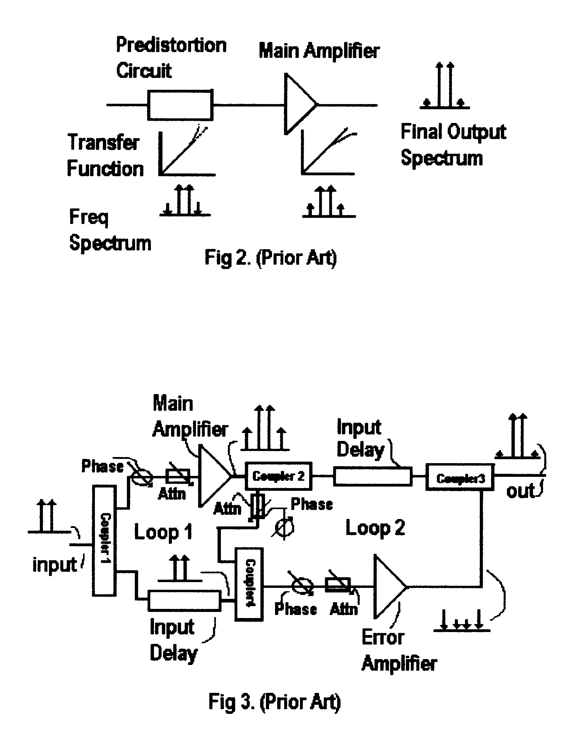
Because of the difficulty in creating the right transfer characteristic over all input conditions a predistorter only provides cancellation of 3.sup.rd order products and are limited to the narrow maximum input level range of the amplifier.
Predistorters also reduce the gain of the overall amplifier by the amount of loss of the predistorter circuit.
These use memory-based circuitry or base band frequency control and are usually narrower band and much more complex than non-adaptive types.
In actual practice is impossible to maintain a perfect balance over a range of frequencies and operating conditions such as input drive, temperature, and tolerances of components.
This problem results in a lower level of efficiency.
A significant deficiency of the feedforward configuration occurs when the Main Amplifier is used above the point where gain compression starts.
The un-balance causes the level of the error signal to increase significantly driving the error amplifier to become non-linear and feed new distortion back into the output.
The referenced patents also have similar difficulties as the standard configuration when the signal levels crossover to the gain compression region of the Main amplifier thereby causing 1.sup.st loop imbalance and injection of intermodulation products into the output.
The use of predistortion with feedforward techniques is needed to operate above the gain compression point area of the main amplifier but at a much added circuit complexity.

Method used


Image

  • Reflect forward adaptive linearizer amplifier
  • Reflect forward adaptive linearizer amplifier
  • Reflect forward adaptive linearizer amplifier

Examples


embodiment

FIG. 5--Alternative Embodiment

FIG. 5 is an alternative embodiment consisting of amplifiers in parallel to increase the power capability of the assembly-15 in FIG. 1. (Two or more amplifiers can be used in parallel to increase the output power.)

The amplifiers can also consist of Push-Pull configuration, Cascode, Distributed etc. Multistage amplifiers can be used, however, the linearization capabilities will be limited because the distortion-cancellation signal will be a reflection of the first stage and not the output stage. (The output stage is normally the most non-linear stage in a well-designed multistage power amplifier.) In the case of multistage amplifier with a FIG. 5 configuration the assembly may act more similar to a predistortion type with limited cancellation capability over a narrower input signal level range.

Operation of the Invention

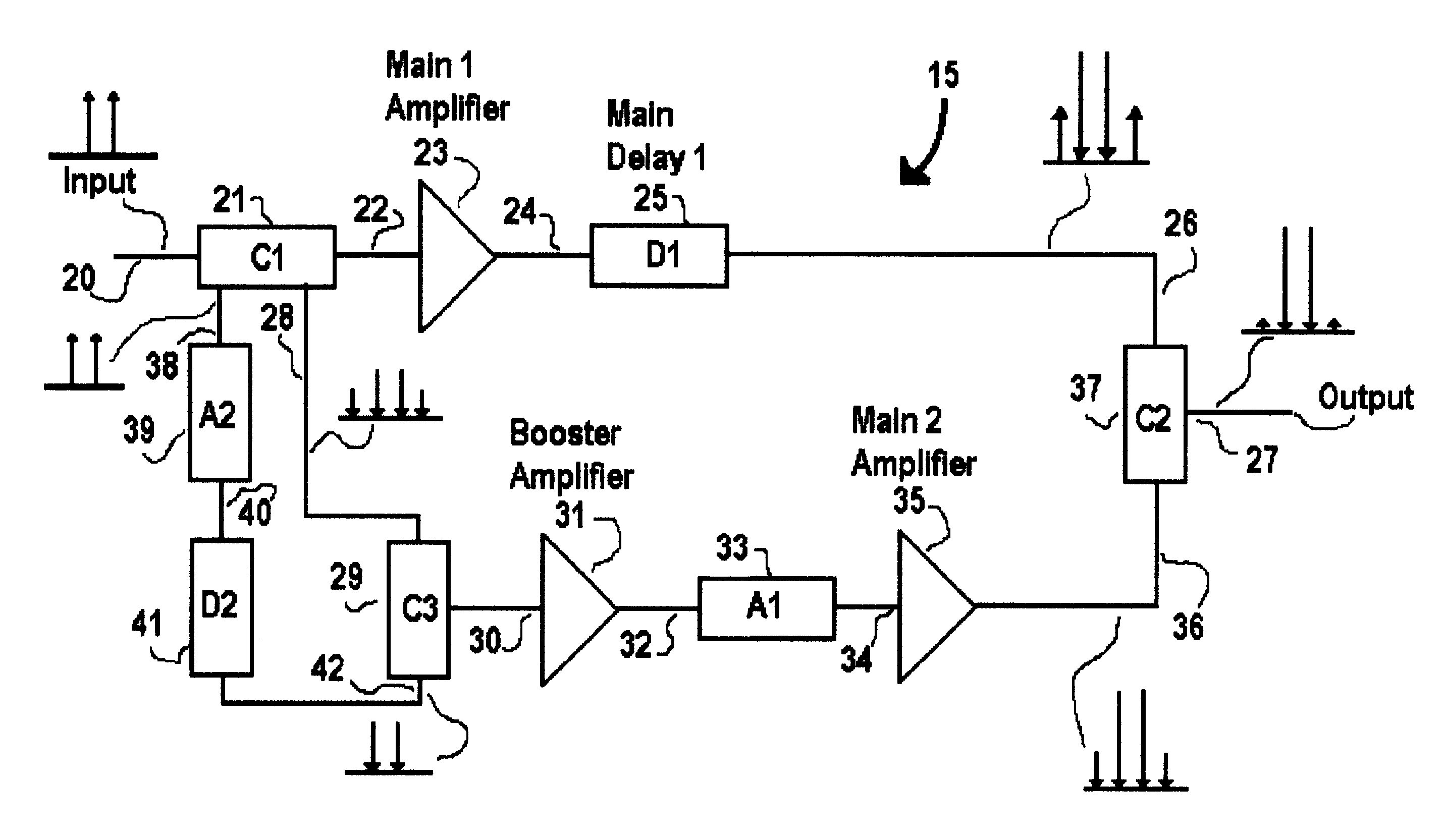
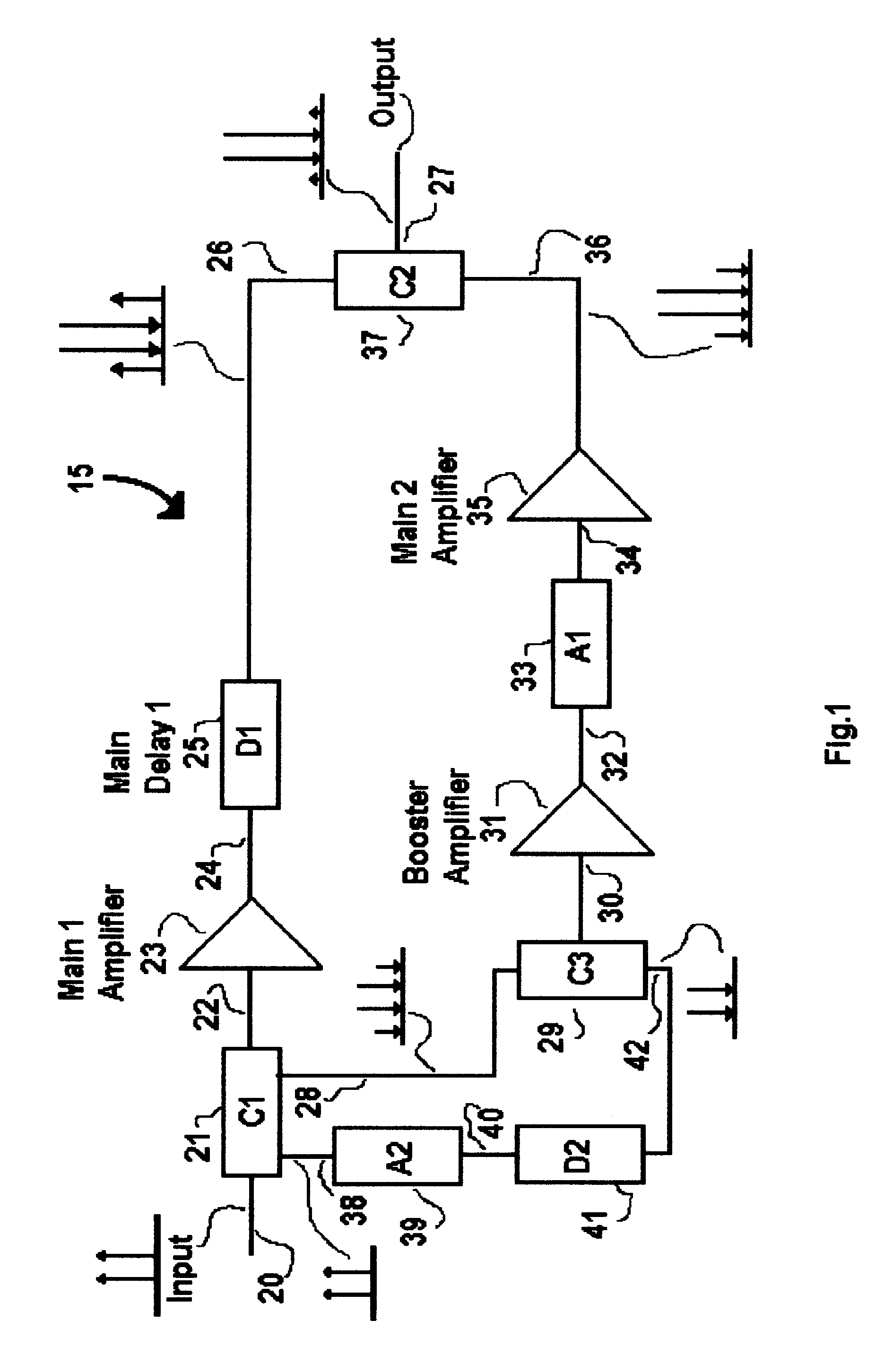
FIG. 1 shows a perspective view of the basic version of the Reflect Forward Adaptive Linearizer Amplifier Assembly ("RFAL" Amplifier). Th...


PUM


Abstract

The Reflect Forward Adaptive Linearizer Amplifier (RFAL Amplifier) assembly (15) in FIG. 1 provides a linerizing method that uses the input reflected signal of the Main 1 Amplifier (23) to develop an intermodulation-correcting signal. The invention incorporates a directional coupler at the input of the Main 1 amplifier that samples and sums the input reflected signal from the Main 1 Amplifier and the forward fundamental input signal to form a distortion-correcting signal that contains both the fundamental and the distortion products of the output. By proper delay and amplification of this correcting signal, it can then be used to drive another Main amplifier (35) to both cancel the output distortion products and double the output power of the Main 1 Amplifier with significant improvement of the overall linearity and efficiency of the final amplifier assembly. The technique allows the use of lower cost transistor up to the Pout at the 1-dB Gain Compression Point with significant distortion cancellation.

Description

REFERENCE CITEDOther ReferenceBook entitled: Feedforward Linear Power Amplifiers. Nick Pothecary. Artech House, 1999. Pages 124-192BACKGROUND--Field of InventionThis invention relates to a multi-tone, high frequency, and high power linearizer amplifier with low intermodulation distortion. Similar type of amplifiers uses predistortion or feedforward circuits or a combination of both. These amplifiers are typically used in wireless telecommunications applications and can be used in other applications requiring a high level of linearity including fiber optic and military systems.BACKGROUND--Description of Prior ArtWhen amplifiers are used at their high power range of their capability they become non-linear. Non-linear operation results in distortion of the input signal at the output of an amplifier. Distortion products that fall in adjacent active channels cause unwanted interference. New wireless communication signals have high peak-to-average ratio causing amplifiers to temporarily o...

Claims


Application Information

Patent Timeline
Patent Type & Authority Patents(United States)
IPC IPC(8): H03F1/32
CPCH03F1/3229
Inventor GUTIERREZ, ROMULO
Owner GUTIERREZ ROMULO
Learn More