Automatic empty container return machine equipped with self-cleaning arrangement

a self-cleaning and empty container technology, applied in the direction of cleaning, conveyor parts, hollow article cleaning, etc., can solve the problems of damage to the installation damage to the cleaning equipment of the machine, and the functional capabilities of the automatic return machine are affected, so as to eliminate the problem of cramped space, avoid the type of damage, and optimize the cleaning of the machine

Inactive Publication Date: 2003-06-10
WINCOR NIXDORF INT
View PDF18 Cites 25 Cited by
  • Summary
  • Abstract
  • Description
  • Claims
  • Application Information

AI Technical Summary

Benefits of technology

The present invention overcomes the aforementioned problems by providing an automatic return machine of the above-stated type being equipped with a cleaning arrangement for performance of self-cleaning of the automatic return machine, which cleaning arrangement is integrated into the machine. The cleaning arrangement is provided constructionally with the machine so that even sites normally difficult to access can be reached. Problems due to cramped space are eliminated since the cleaning arrangement is already disposed at its intended location. Such prepositioning of the cleaning arrangement on the machine permits optimal and efficient cleaning of the machine and avoidance of the type of damage that is possible with manual cleaning. In addition, working time is saved since the automatic return machine, in effect, cleans itself.
Also possible is cleaning as needed, wherein the degree of contamination can be determined by manual inspection or also, in an advantageous implementation of the present invention, automatically through sensors. The data sensed by the sensors can be transferred to a central control unit of the machine which, at a predetermined degree of contamination, stops the normal operation of the machine and initiates the self-cleaning process. If several machines are available in a supermarket or the like, the consequences of placing a machine out of operation can be managed by switching over to another machine so that the operation of the self-cleaning arrangement can take place immediately on the contaminated machine. Otherwise, given the corresponding programming, the operation of the self-cleaning arrangement can be offset in time, for example, by being shifted into nighttime hours.
It is further of advantage if the parts to be cleaned are provided with a special surface coating, which ensures low adhesion of dust and dirt particles, for example, coatings which are applied by means of nanotechnology. For the complete removal of liquid residues, fans can be employed which blow warm or cold air onto the parts to be cleaned.

Problems solved by technology

Since, as a rule, the empty containers contain residual liquids, which can flow out during the handling of the empty containers in the automatic return machine, after a certain length of operation heavy contaminations of the processing units, transport stages, sensors, etc. can occur which impair the functional capabilities of the automatic return machine.
This is very expensive and also difficult given the cramped conditions of space in the automatic return machine, such that the quality of the cleaning suffers.
Moreover, during this cleaning activity, installations in the automatic return machine could be damages.

Method used


Image

  • Automatic empty container return machine equipped with self-cleaning arrangement
  • Automatic empty container return machine equipped with self-cleaning arrangement
  • Automatic empty container return machine equipped with self-cleaning arrangement

Examples


first embodiment

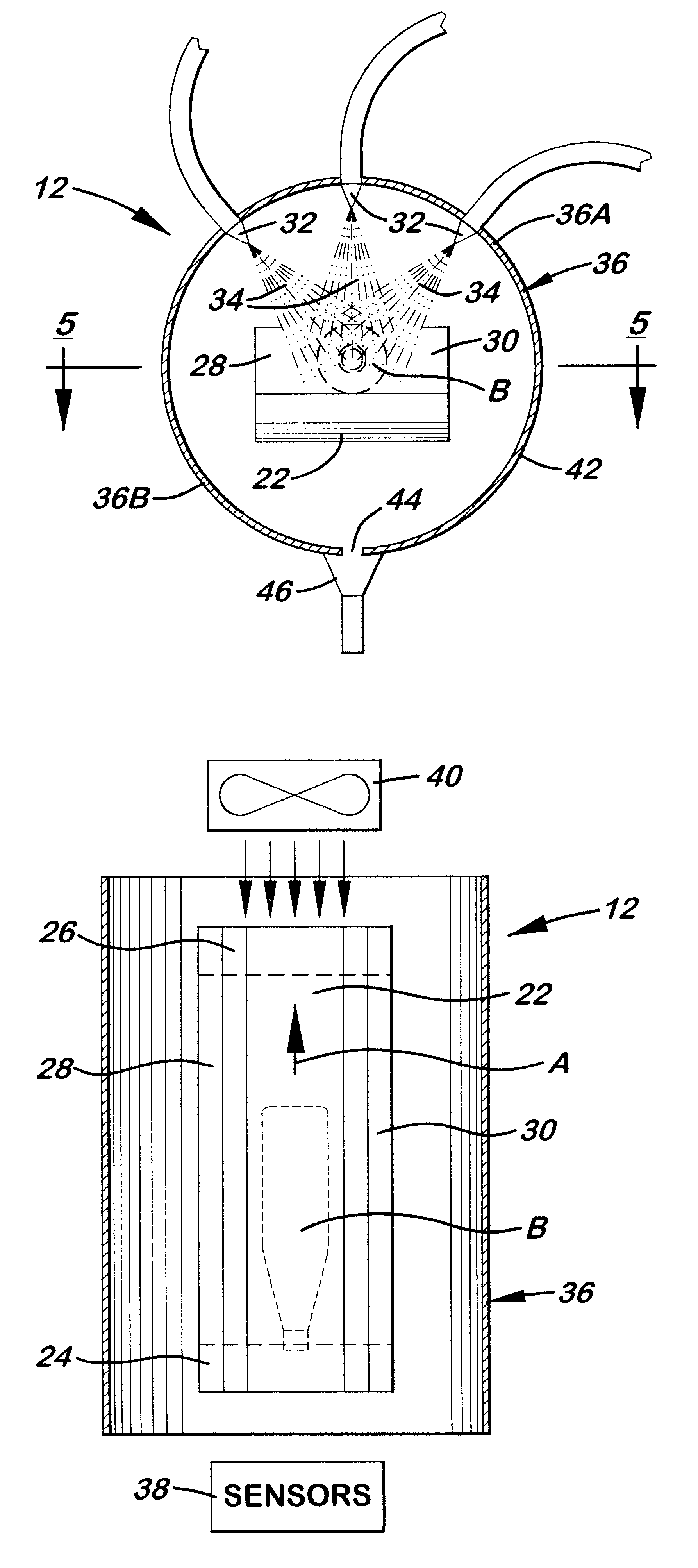
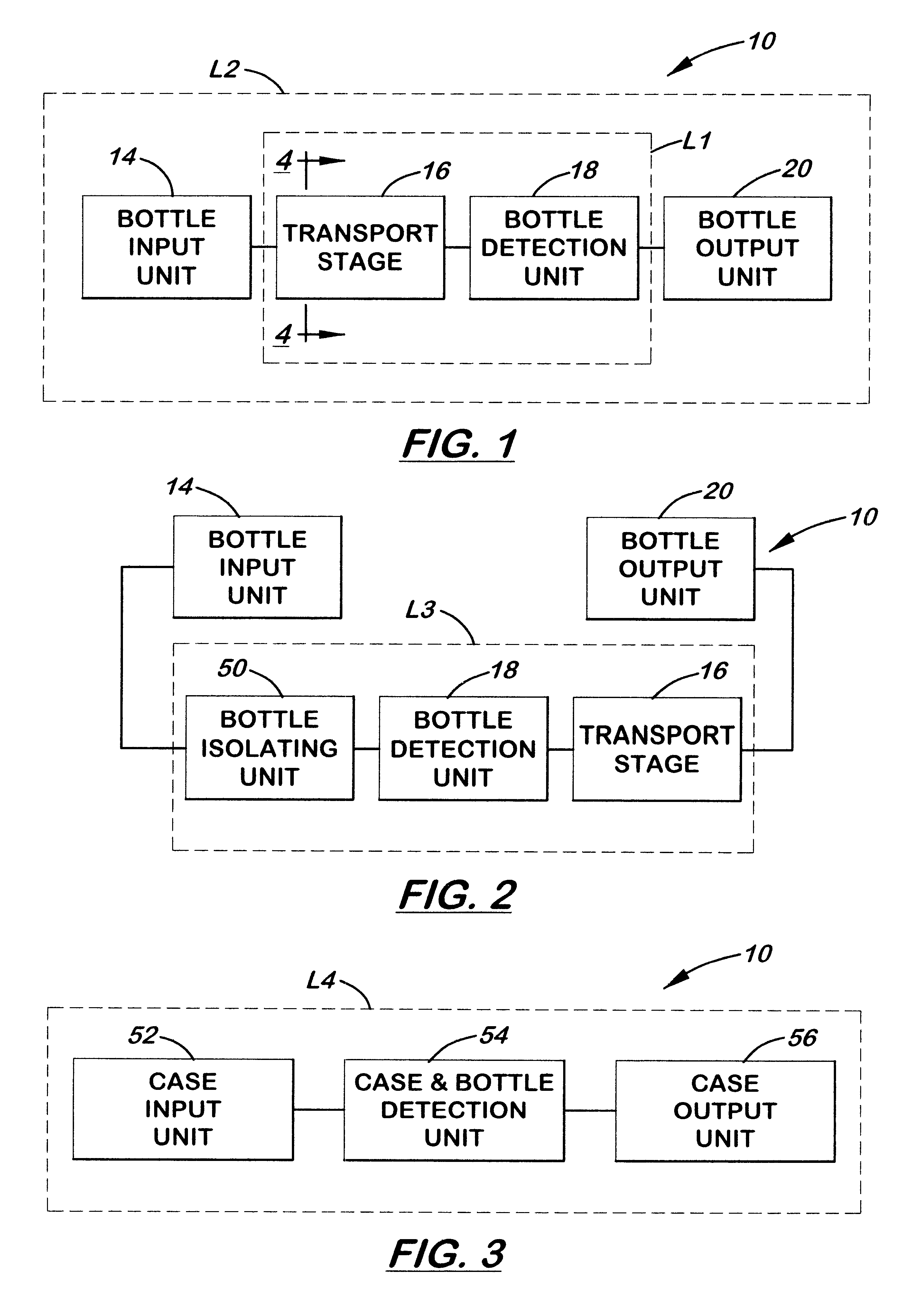
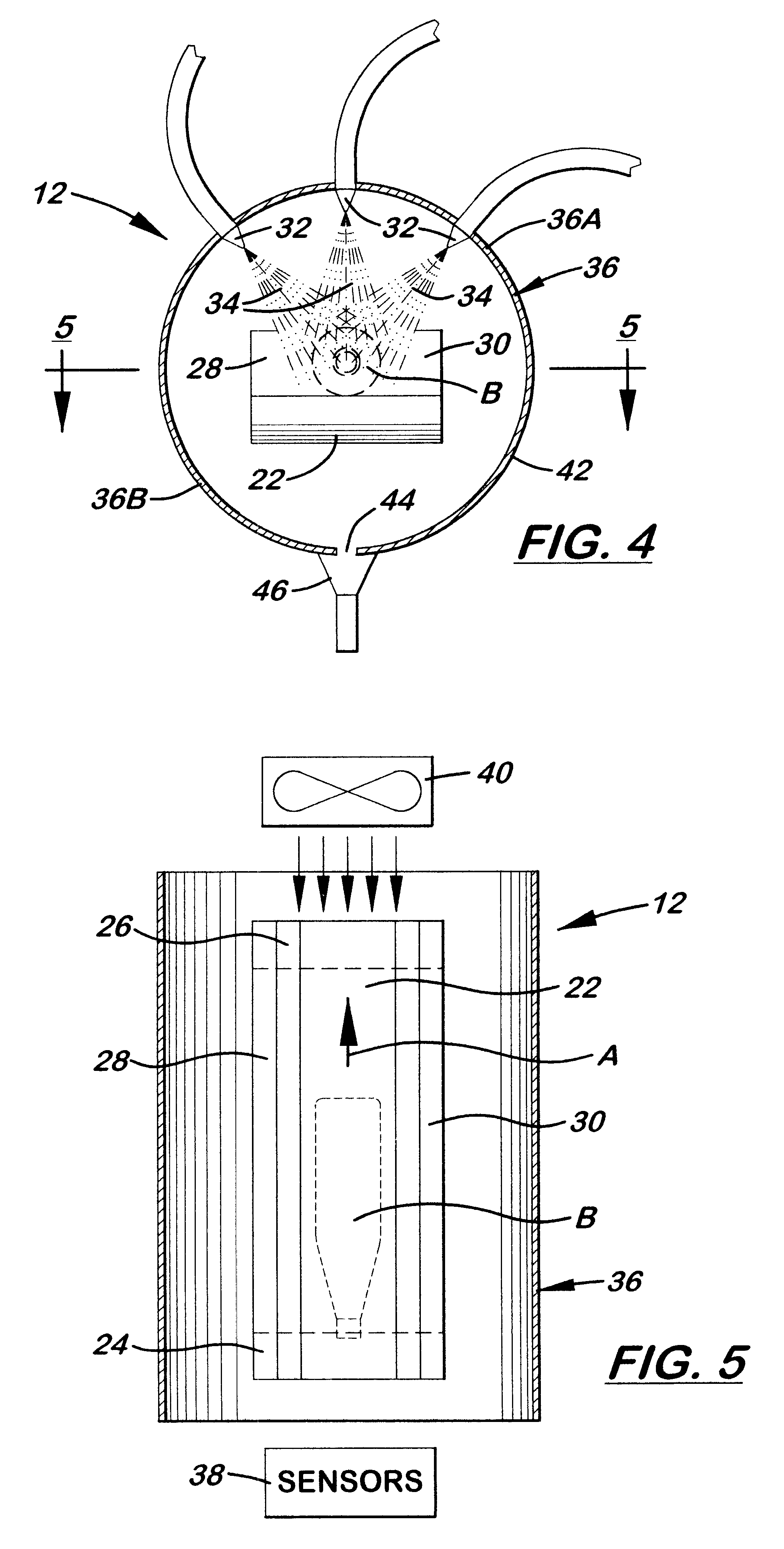
Referring to the drawings and particularly to FIGS. 1, 4 and 5, there is illustrated in FIG. 1 a schematic flow chart representing an automatic bottle return machine, generally designated 10, adapted for processing containers in the form of bottles B, as shown in dot-dash line form in FIGS. 4 and 5, and being equipped with a self-cleaning arrangement 12, as shown in FIGS. 4 and 5, in accordance with the present invention. The machine 10 includes a bottle input unit 14, a transport stage 16, a bottle detection unit 18, and a bottle output unit 20. The bottle input unit 14 can be, for example, a turnstile (not shown) with an oblique axis and compartments in which bottles are placed individually in an inclined, or obliquely, downward orientation with the opening of the bottle pointing toward the operator. From the bottle input unit 14 the bottles B arrive at the transport stage 16 which is implemented as a conveyor belt 22 being shown in FIGS. 4 and 5. The conveyor belt 22 transports e...

third embodiment

In the case of the smaller self-cleaning area L1 depicted in FIG. 1, the self-cleaning arrangement 12 further includes another tubular encapsulating envelope, substantially the same as the envelope 36 described above, which encompasses the bottle detection unit 18 such that the envelopes 36 of the transport stage 16 and bottle detection unit 18 seamlessly merge one into the other. The self-cleaning arrangement 12 also includes additional cleaning nozzles 22 and, optionally, cleaning brushes 48 (such as shown in FIG. 6 with respect to the machine 10) disposed in the area of the bottle detection unit 18. Since in its operation, the bottle detection unit 18 utilizes light beams and includes optical components, such as light barriers, optical sensors and image detection devices, the tubular encapsulating envelope 36 must be light-transmissive at least in the areas of beam penetration. This can be realized through corresponding windows, for example comprised of acrylic glass. It is under...


PUM


Abstract

An automatic empty container return machine includes a detection unit operable for identifying whether or not an empty container is of a predetermined category, an input unit located upstream of the detection unit for receiving empty containers to supply the empty containers to the detection unit, an output unit located downstream of the detection unit for receiving empty containers that have been identified by the detection unit as being of the predetermined category, a transport stage having a conveyor for transporting empty containers from the input unit through the detection unit to the output unit, and a self-cleaning arrangement having components integrated with at least one of the input unit, detection unit, output unit and transport stage and being operable at selected times to clean surfaces thereof that are preselected to be cleaned.

Description

BACKGROUND OF THE INVENTION1. Field of the InventionThe present invention relates to an automatic return machine for empty containers and, more particularly, is concerned with an automatic empty container return machine equipped with a self-cleaning arrangement for performance of cleaning of the machine.2. Description of the Prior ArtIn German patent document No. DE 195 08 388 A1, there is disclosed a system for processing reusables which employs an automatic return machine for processing reusable containers, in particular, reusable cups. After consuming a drink, a consumer supplies the used cup to the automatic return machine in which the cup is tested for system conformity. If the cup is detected as being within the scope of the reusables system, return of the cup deposit money to the consumer takes place. The automatic return machine places such reusable cups in magazine type tubes or cases which are then transported to a separate service center. At the separate service center, t...

Claims


Application Information

Patent Timeline
Patent Type & Authority Patents(United States)
IPC IPC(8): G07F7/00G07F7/06
CPCB08B9/28G07F7/0609B08B9/36
Inventor LONING, JOHANNHECHT, SIEGMAR
Owner WINCOR NIXDORF INT
Why Eureka
Try Eureka