Bi-directional optical switch

a bi-directional optical switch and switch technology, applied in the field of non-mechanical optical switches, can solve the problems of reducing the amplitude of the optical signal, not being widely adopted, and losing a large amount of signal strength,

Inactive Publication Date: 2003-06-10
AGILTRON
View PDF6 Cites 33 Cited by
  • Summary
  • Abstract
  • Description
  • Claims
  • Application Information

AI Technical Summary

Problems solved by technology

However, it has not been widely adopted because its lack of reliability and its high cost associated with its fabrication difficulty.
In an optical switch, light signal must be accurately entered into an optical fiber, or much of the signal strength will be lost.
Additional insertion losses reduce the amplitude of the optical signal.
Most prior art optical switches are based on mechanical movement to switch light beams, consequently have drawbacks of slow and less reliable.
This type of switch has a deficiency of large insertion loss due to fiber to thin film waveguide coupling.
This type of device, consequently, has undesirable properties of slow operation at low temperature and electrodes in the light path (for example U.S. Pat. No. 4,917,452).
However, all known magneto-optic switch designs are limited to transmit light only in one direction.
This deficiency hampers their applications in today's optical networks, which are often bi-directional.
Moreover, due to their complex configurations, conventional optical switches also suffer from high insertion loss and high cost.
Further, these switches often comprise many elements and require extremely stringent alignment that is unsuitable for manufacture.
Therefore, magneto-optic based optical switches have not been widely used in optical communications.
The switch is a modification of optical circulator thus has a drawback of non-reciprocal operation.
Because of the large beam separations between the two adjacent lenses, the design requires large and long crystals to deflect the beams.
As a result, the optical device typically has large loss, excessively large size, and is expensive to produce.
However, Shirasaki switch is a non-reciprocal device, which is unsuitable for modern bi-directional communication applications.
Another disadvantage of Shirasaki switch is that the beam propagations are no long parallel rather with an angle.
Therefore, manufacturing of Shirasaki switch is difficult.
With a long and fold beam propagation and an unsymmetrical geometry, the devices become less tolerance to both extremely small angle and position misalignment.
This type of switch is therefore often very difficult and costly to make.
Moreover, the design is a non-reciprocal device.

Method used


Image

  • Bi-directional optical switch
  • Bi-directional optical switch
  • Bi-directional optical switch

Examples


Embodiment Construction

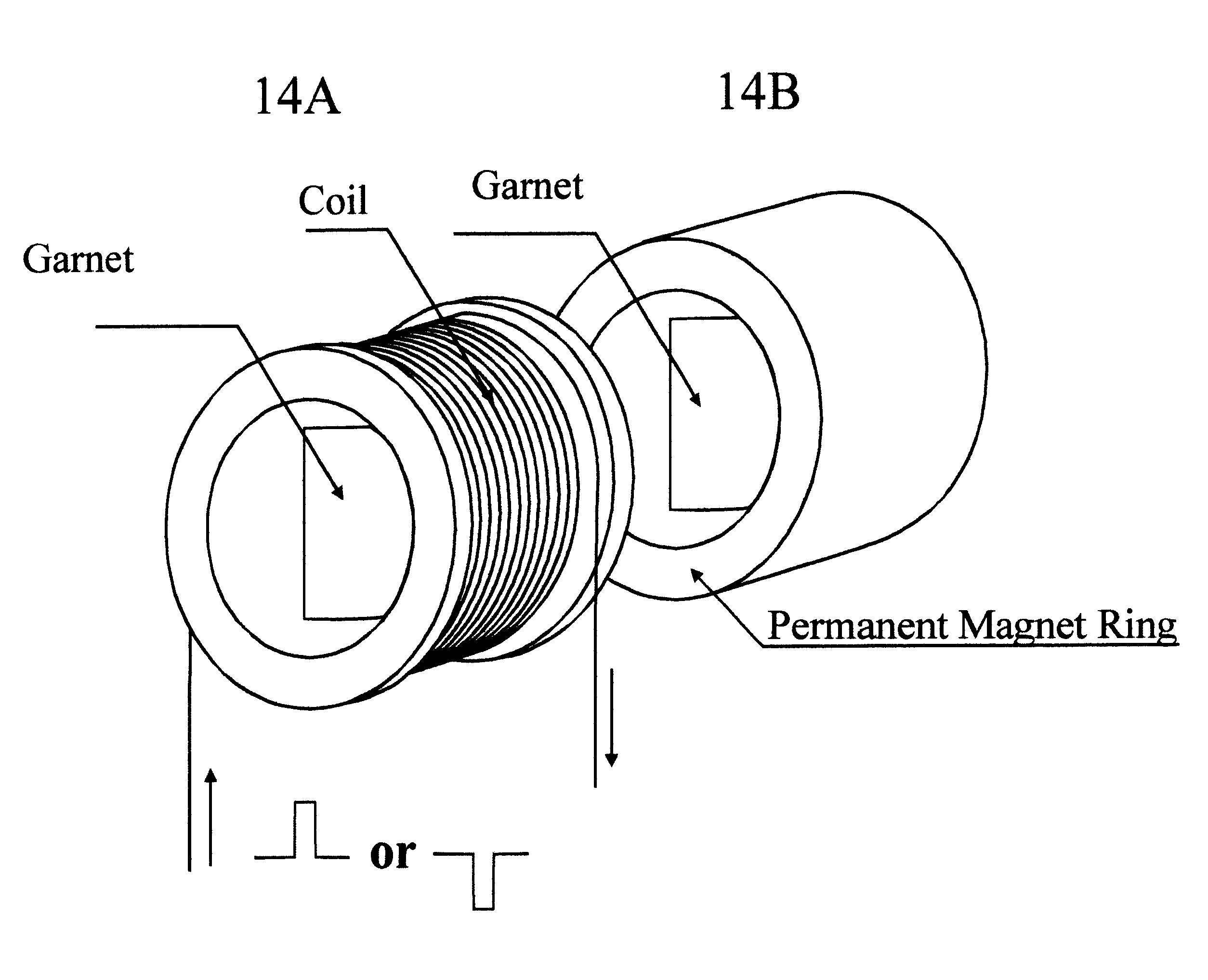
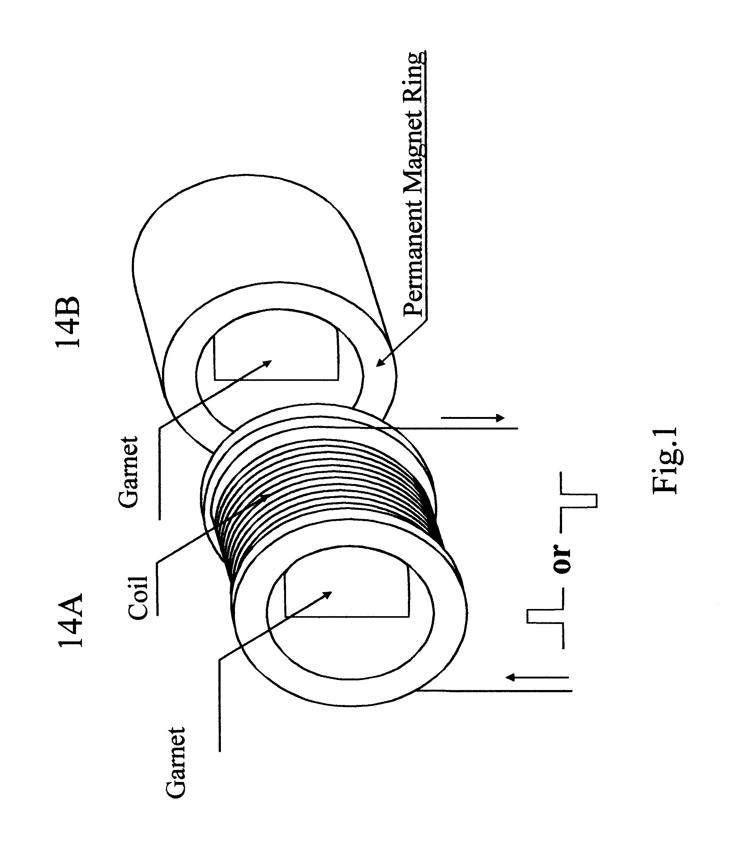
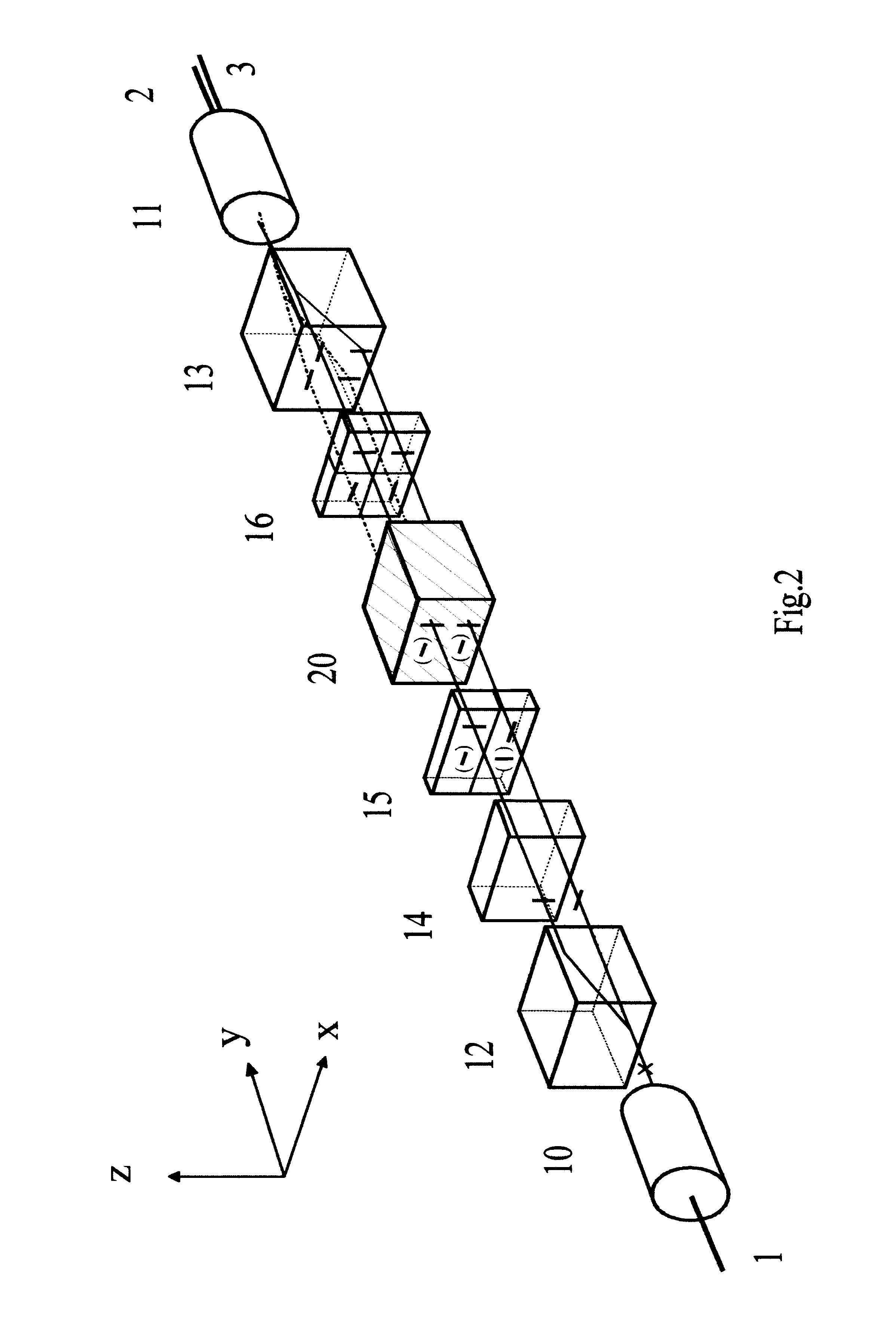
The polarization insensitive solid-state optical switch of this invention has several advantages over prior non-mechanical optical switches. First, the inventive reciprocal Faraday rotator 14 enables light beam to propagate in both directions. The embodiment of the inventive switch is a reciprocal optical device, which advantageously allows bi-directional communications. Conventional magneto-optic switches are all limited to non-reciprocal operation. Second, the two optical ports on the same side are placed next to each other and share the same imaging element. Only one lens is used on each side of the switch, leading to fewer optical elements and a smaller footprint. Conventional optical switches have an arrangement wherein each optical port has its own individual imaging element. Third, the incorporation of a beam angle correction system 20 compensates for the angle separation between the two beams from the same imaging lens (dual collimator consisting fiber 2 and fiber 3). The ad...


PUM

PropertyMeasurementUnit
diametersaaaaaaaaaa
Curie temperatureaaaaaaaaaa
optically transparentaaaaaaaaaa

Abstract

The present invention provides improved optical switches in which no mechanical movement is required to direct optical pathways between plural fiber ports and light transmission is bi-directional. Advantageously, the inventive switches permit bi-directional light transmission. The inventive switches also incorporate light bending devices to allow two fibers to be coupled to the light beams using a single lens for compactness. In the inventive switch, an optical signal is spatially split into two polarized beams by a birefringent element, which passes through a polarization rotation device that comprises waveplates, walk-off elements, and an electrically controllable polarization rotator, and recombine into an output fiber, achieving polarization independent operation. The switches of the present invention rely on electro-magnetically or electro-optically switching the beam polarizations from one state to another to rapidly direct the light path.

Description

1. Field of the InventionThe present invention is related to optical devices; more particularly, the invention relates to non-mechanical optical switches.2. Description of Related ArtOptical switch is a device for directing optical signals along selected fibers of an optical network, in which light signals are transmitted along optical fibers to transfer information from one location to another. The desirable optical switch performance include: high speed switching, bi-direction operation, low optical insertion loss, long operation lifetime, small size, and low cost. Optical switch is a key component in today's optical network, analogous to the electrical switches in electrical networks. However, it has not been widely adopted because its lack of reliability and its high cost associated with its fabrication difficulty.In an optical switch, light signal must be accurately entered into an optical fiber, or much of the signal strength will be lost. The alignment requirements of modem s...

Claims


Application Information

Patent Timeline
Patent Type & Authority Patents(United States)
IPC IPC(8): G02F1/01G02F1/09G02F1/31G02F1/29G02B6/26G02B6/35
CPCG02B6/2746G02F1/31G02F1/093G02B6/355
Inventor JIN, GUANGHAIZHANG, LEIZHAO, JING
Owner AGILTRON
Why Eureka
Try Eureka