Method and device for measurement of nanometer resolution total reflection differential micrometric displacement

A total reflection and differential technology, applied in measurement devices, optical devices, instruments, etc., can solve the problems of limited resolution, expensive system, influence, etc., and achieve the effect of improving sensitivity

Inactive Publication Date: 2011-07-13
ZHEJIANG UNIV
View PDF5 Cites 17 Cited by
  • Summary
  • Abstract
  • Description
  • Claims
  • Application Information

AI Technical Summary

Problems solved by technology

However, its resolution is limited by the size of the pinhole and the numerical aperture of the microscope objective, and is affected by the fluctuation of the external background and the light source itself.
In order to improve its axial resolution, Zhao Weiqian and others proposed the idea of ​​differential confocal in the Chinese invention pat

Method used


Image

  • Method and device for measurement of nanometer resolution total reflection differential micrometric displacement
  • Method and device for measurement of nanometer resolution total reflection differential micrometric displacement
  • Method and device for measurement of nanometer resolution total reflection differential micrometric displacement

Examples


Embodiment 1

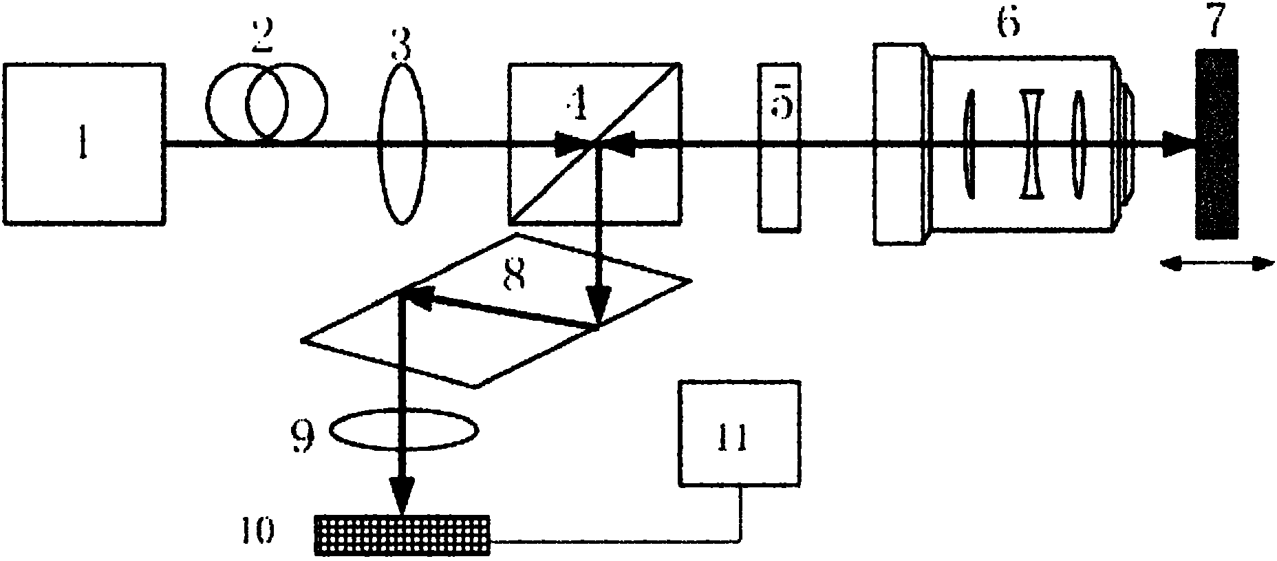
[0042] Such as figure 1 As shown, a device for measuring nanometer-resolution total reflection differential micro-displacement, including: laser 1, single-mode fiber 2, collimator lens 3, polarization beam splitter 4, λ / 4 wave plate 5, microscope objective lens 6, the measured A target mirror 7 , a rhombic prism 8 , a convex lens 9 , a differential detector 10 , and a drive and display unit 11 .

[0043] The laser 1, the single-mode optical fiber 2 and the collimating lens 3 constitute the first component group in sequence, the polarization beam splitter 4 is the second component group, and the first component group and the second component group are sequentially located on the optical path of the light emitted by the laser 1; The λ / 4 wave plate 5 and the microscopic objective lens 6 constitute the third component group, which are sequentially located on the first transmission light path of the polarization beam splitter 4 with the target lens 7 to be measured; the rhomboid pris...

Embodiment 2

[0058] Such as Figure 7 As shown, a device for measuring nanometer-resolution total reflection differential micro-displacement, including: laser 1, single-mode fiber 2, collimator lens 3, polarization beam splitter 4, λ / 4 wave plate 5, microscope objective lens 6, the measured A target mirror 7 , a rhombic prism 8 , a convex lens 9 , a differential detector 10 , and a drive and display unit 11 .

[0059] The laser 1, the single-mode optical fiber 2 and the collimating lens 3 constitute the first component group in sequence, the polarization beam splitter 4 is the second component group, and the first component group and the second component group are sequentially located on the optical path of the light emitted by the laser 1; The λ / 4 wave plate 5 and the microscopic objective lens 6 constitute the third component group, which are sequentially located on the first reflected light path of the polarizing beam splitter 4 with the measured target mirror 7; the rhomboid prism 8, c...


PUM

PropertyMeasurementUnit
Wavelengthaaaaaaaaaa

Abstract

The invention discloses a method and device for measurement of nanometer resolution total reflection differential micrometric displacement. The device comprises a laser device, a single-mode fiber, a collimating lens, a polarizing beam splitter, a lambda/4 wave plate, a micro objective, a detected target lens, a rhombic prism, a convex lens, a differential detector and a driving and display unit. The method comprises steps as follows: after being filtered, collimated and split by polarization, laser sequentially passes through a fast axis and the lambda/4 wave plate and micro objective to reach the detected target lens, wherein the included angle between the lambda/4 wave plate and micro objective and the polarization direction of vertical incidence light beam is 45 degrees; after being reversed, the laser passes through the micro objective and lambda/4 wave plate, and then vertically enters the polarizing beam splitter again; then, the laser enters the rhombic prism, is subjected to total reflection in the rhombic prism, and exits; and finally, after being collected, the laser enters the differential detector for processing, thus obtaining a signal for reflecting the position change of the detected target lens, and displaying the position change of the detected target lens. The invention can be used for detecting the manometer resolution and can be widely applied to the industrial precision measurement and monitoring fields.

Description

technical field [0001] The invention belongs to the technical field of photoelectric detection, and in particular relates to a method and a device for high-precision micro-displacement measurement and monitoring. Background technique [0002] Today, nanotechnology, biotechnology, and high-end integrated circuit manufacturing technology have become important directions for the development of world science and technology. Fast and reliable nanoscale resolution detection technology plays an extremely important role in the research of nanotechnology, biotechnology, high-end integrated circuit manufacturing and other fields. The traditional microscopic measurement technology based on light interference has been able to obtain measurement resolutions as high as below 1nm. At present, the optical non-interference method for micro-displacement measurement is the most successful confocal method. The traditional confocal method is to use the point light source, the object to be measu...

Claims


Application Information

Patent Timeline
IPC IPC(8): G01B11/02
Inventor 匡翠方王婷婷库玉龙郝翔刘旭
Owner ZHEJIANG UNIV
Why Eureka
Try Eureka