Driver circuit having a slew rate control system with improved linear ramp generator including ground

a technology of linear ramp generator and drive circuit, which is applied in the direction of pulse manipulation, pulse technique, instruments, etc., can solve the problems of ineffective single cascoded solution, power limitation, and inability to achieve the desired linearity increas

Inactive Publication Date: 2003-07-01
STMICROELECTRONICS SRL
View PDF16 Cites 34 Cited by
  • Summary
  • Abstract
  • Description
  • Claims
  • Application Information

AI Technical Summary

Problems solved by technology

Such an auxiliary supply if present, however, is power limited; the desired voltage can be supplied but at a modest current level.
Generally, problems in achieving the desired linearity increase as the supply voltage is increased.
However, a single cascoded solution is not effective because it is not capable of ramping down to zero volts.
The inability to go to zero volts is unacceptable for a high performance drive.
Similar problems are encountered with current mirrors or cascoded current mirrors made up of MOSFET (metal-oxide-semiconductor-field-effect-transistor) devices.
Basic MOSFET current mirrors are also limited as far as providing good linearity in ramping with voltages encountered in integrated, circuit charge pump supplies.
Cascode connected MOSFETs provide a better deg...

Method used


Image

  • Driver circuit having a slew rate control system with improved linear ramp generator including ground
  • Driver circuit having a slew rate control system with improved linear ramp generator including ground
  • Driver circuit having a slew rate control system with improved linear ramp generator including ground

Examples


first embodiment

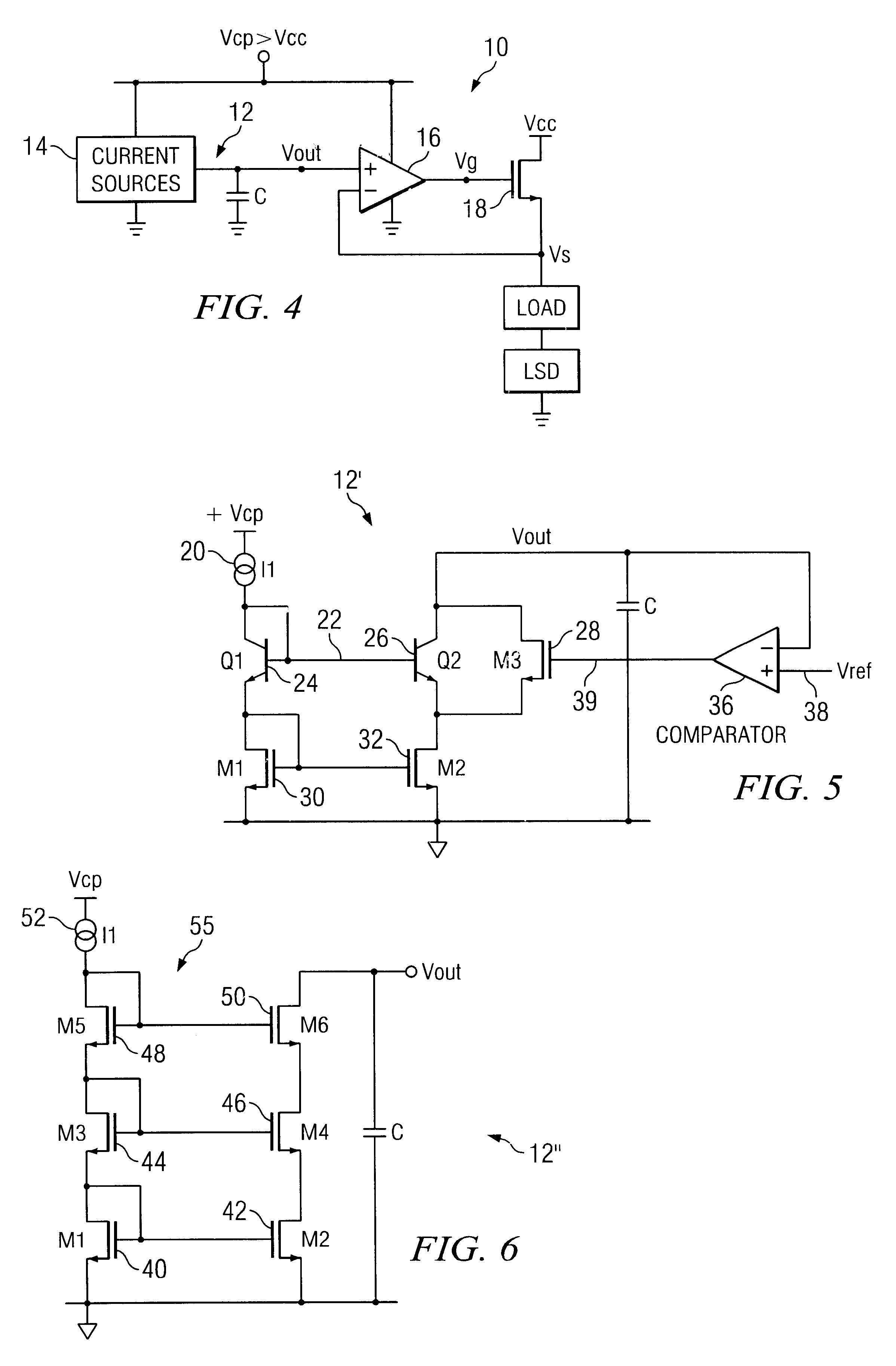
Referring now to FIG. 5, a voltage ramp generator 12' in accordance with the present invention is illustrated. Voltage ramp generator 12', unlike the prior art solutions, employs a cascoded current source 22 (as opposed to two current sources) having a cascode-connected pair of current mirrors. Voltage ramp generator 12' has the elements shown in the figure, including I1 reference current 20, Q1 bipolar transistor 24, Q2 bipolar transistor 26, M1 MOSFET 30, M2 MOSFET 32, M3 MOSFET 28, capacitor C, and comparator 36. Cascoded current source 22 has a current mirror is formed by M1 transistor 30 and M2 transistor 32 in current mirror formation, with diode-connected M1 transistor 30 in the reference leg and M2 transistor 32 in the mirror leg, Q2 cascode device 26, and diode-connected Q1 biasing device 24. For simplicity, only the sink or discharging cascoded current source of voltage ramp generator 12 is shown; one of ordinary skill in the art will recognize that a current source may be...

second embodiment

The voltage ramp generator 12" of the invention provides a simple, yet elegant, approach to providing an output voltage between a maximum voltage and ground that is highly linear. No decision-making element, such as a comparator, or switching mechanism is needed to practice this embodiment since the linear discharge of capacitor C is accomplished automatically. Only MOSFET devices are used to automatically adjust Vout while maintain high output impedance, further adding to the linearity that is achieved. Moreover, the costs attendant with combining bipolar and MOS technologies are avoided.

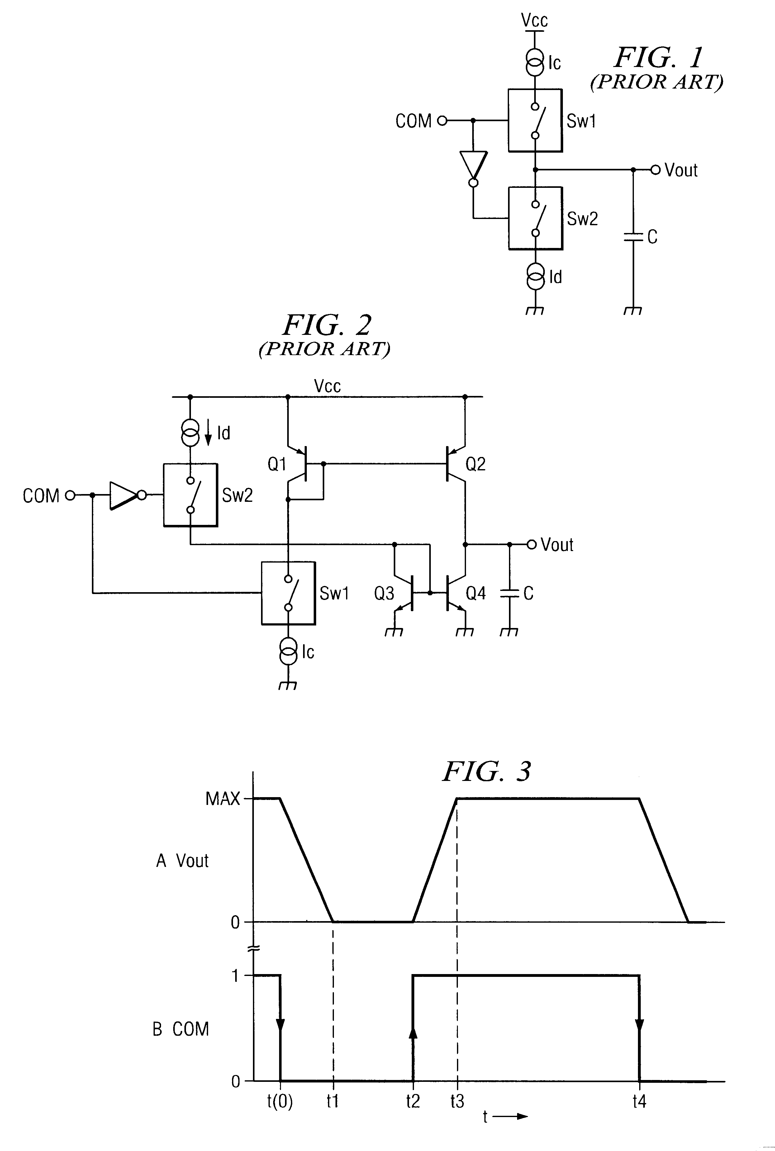
While the embodiment of FIG. 6 generally provides a highly linear ramp down of Vout towards ground, there is a slight deviation from linearity in the ramp when the ramp voltage Vout gets extremely close to ground and M2 MOSFET device 42 goes into the linear or low resistance region. This occurs after M6 and M4 MOSFET devices 50, 46 go into the linear region and thus FIG. 2 is effectively represente...

third embodiment

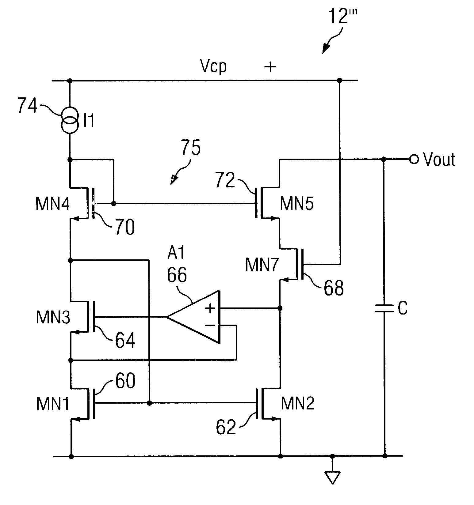
Referring now to FIG. 8, the present invention that overcomes this slight deviation in linearity and thus can ensure a linear ramp down of Vout to ground is illustrated. Voltage ramp generator 12'" overcomes the mirror error illustrated in FIGS. 7A and 7B by ensuring that the transistor in the reference leg of the current mirror is in the same region of operation as the transistor in the mirror leg of the current mirror, regardless of the region of operation of the mirror leg transistor. The circuitry of FIG. 8 relies upon the fact that the drain voltage of a MOS transistor controls the region in which the transistor will operate and thus is important to providing proper matching between transistors. Voltage ramp generator 12'" has several elements, including 11 reference current 74, MN1, MN2, MN3, MN4, MN5, MN6 MOSFET devices 60, 62, 64, 68, 70, 72, amplifier A1, and capacitor C. Gate-connected MOSFET devices 60 and 62 have their sources coupled to ground. MOSFET device 64 is coupl...


PUM


Abstract

Methods and structures for ensuring the highly linear discharge of a capacitor used for slew rate control of a power driving stage from a maximum voltage to a minimum supply voltage, such as ground. A voltage ramp generator uses a single cascoded current source to achieve the linear ramp-down.

Description

1. Field of the InventionThe present invention relates generally to drive circuits for a power device of a power driving stage, and, more particularly, to a driver circuit operating from a supply voltage (e.g. a charge pump voltage) that is higher than the supply voltage of the power device.2. Description of Related ArtA driver circuit is generally a relatively low power circuit that drives, or controls, a higher power device. The power device may be part of a power driving stage for a load. An example is a load that is a motor, such as a brushless motor, that provides the motive force for a spindle of a hard disk drive. Similar driver circuits are applied elsewhere, such as in voice coil motor (VCM) systems.One of the most widely used types of driver circuits in such applications uses a three-phase brushless motor in a configuration in which current energizes respective motor coils using a full wave bridge configuration. The bridge includes two power stages for each phase, so typic...

Claims


Application Information

Patent Timeline
IPC IPC(8): H03K17/16H03K4/00H03K4/50H03K4/502G05F3/26G11B19/28
CPCG05F3/262G11B19/28H03K4/50H03K17/166H03K4/502
Inventor CALLAHAN, JR., MICHAEL J.
Owner STMICROELECTRONICS SRL
Why Eureka
Try Eureka