Electromagnetic induction device

a technology of induction device and electromagnetic field, which is applied in the direction of transformer/inductance magnetic core, fixed transformer, coil arrangement, etc., can solve the problems of increasing the type of core pieces and, hence, the manufacturing cost, and the inability to compactly assembly the known transformer 64 discussed abov

Inactive Publication Date: 2003-07-01
TABUCHI ELECTRIC CO LTD +1
View PDF10 Cites 29 Cited by
  • Summary
  • Abstract
  • Description
  • Claims
  • Application Information

AI Technical Summary

Benefits of technology

According to the present invention, since no core piece is positioned laterally of the winding member and, therefore, the electromagnetic induction device can have a reduced lateral dimension as measured in a direction perpendicular to the axial direction of the winding member. Moreover, since the bobbin is of a flat configuration having a reduced axial width, the spacing between the core arms of the T-shaped core pieces can be reduced in size, making it possible to form a strong magnetic field whereby an excellent magnetic characteristic can be obtained. Also, since the core pieces have the same shape and size, the number of types of core pieces required to form the core assembly can advantageously be reduced, thereby reducing the manufacturing cost.
In a further preferred embodiment of the present invention, the bobbin may include a plurality of bobbin pieces defined by dividing the bobbin in a direction axially thereof and wherein each of the core pieces is embedded in the corresponding bobbin piece preferably by an insert-molding technique. Since in the electromagnetic induction device embodying the present invention, the core pieces are mounted on and integrated together with the respective bobbin pieces by the use of the insert-molding technique, this design is effective to eliminate the need to employ a manufacturing step of fixing the core pieces by a fixture such as a core clip after the latter have been assembled into the bobbin and, therefore, the number of the manufacturing steps can correspondingly be reduced along with reduction in number of component parts, resulting in reduction in manufacturing cost.

Problems solved by technology

It has, however, been found that the known transformer 64 discussed above has a problem.
As such, the transformer 64 of the structure discussed above is incapable of being assembled compact and requires a relatively large space for mounting on a circuit substrate.
Accordingly, the known transformer 64 requires two types of core pieces of different sizes and this leads to increase of the type of core pieces and, hence, that of the manufacturing cost.
For these reasons, a circuit unit including the transformer 64 mounted on the circuit substrate requires a relatively large space for installation and, therefore, application thereof is limited, thereby constituting a cause of the high frequency heating apparatus incapable of being manufactured compact.

Method used


Image

  • Electromagnetic induction device
  • Electromagnetic induction device
  • Electromagnetic induction device

Examples


first preferred embodiment

(First Preferred Embodiment)

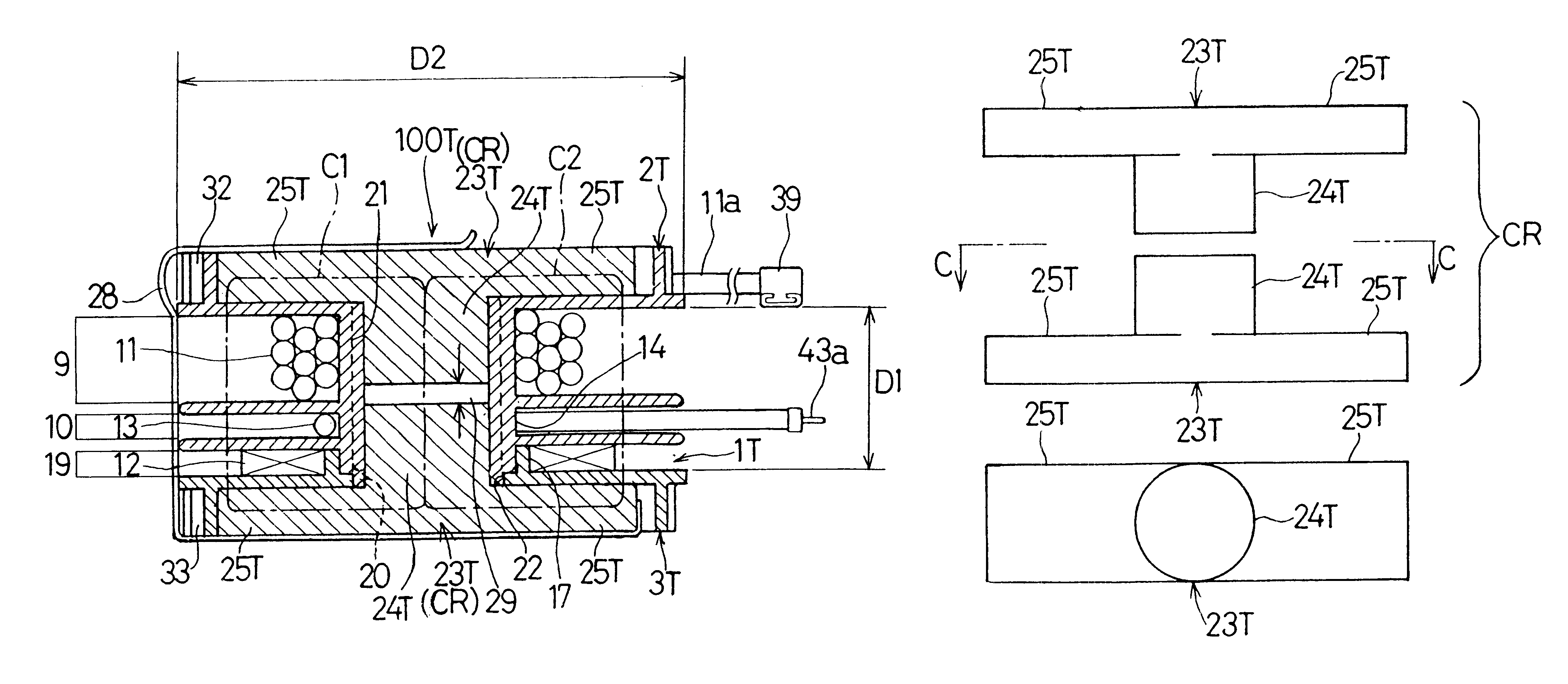
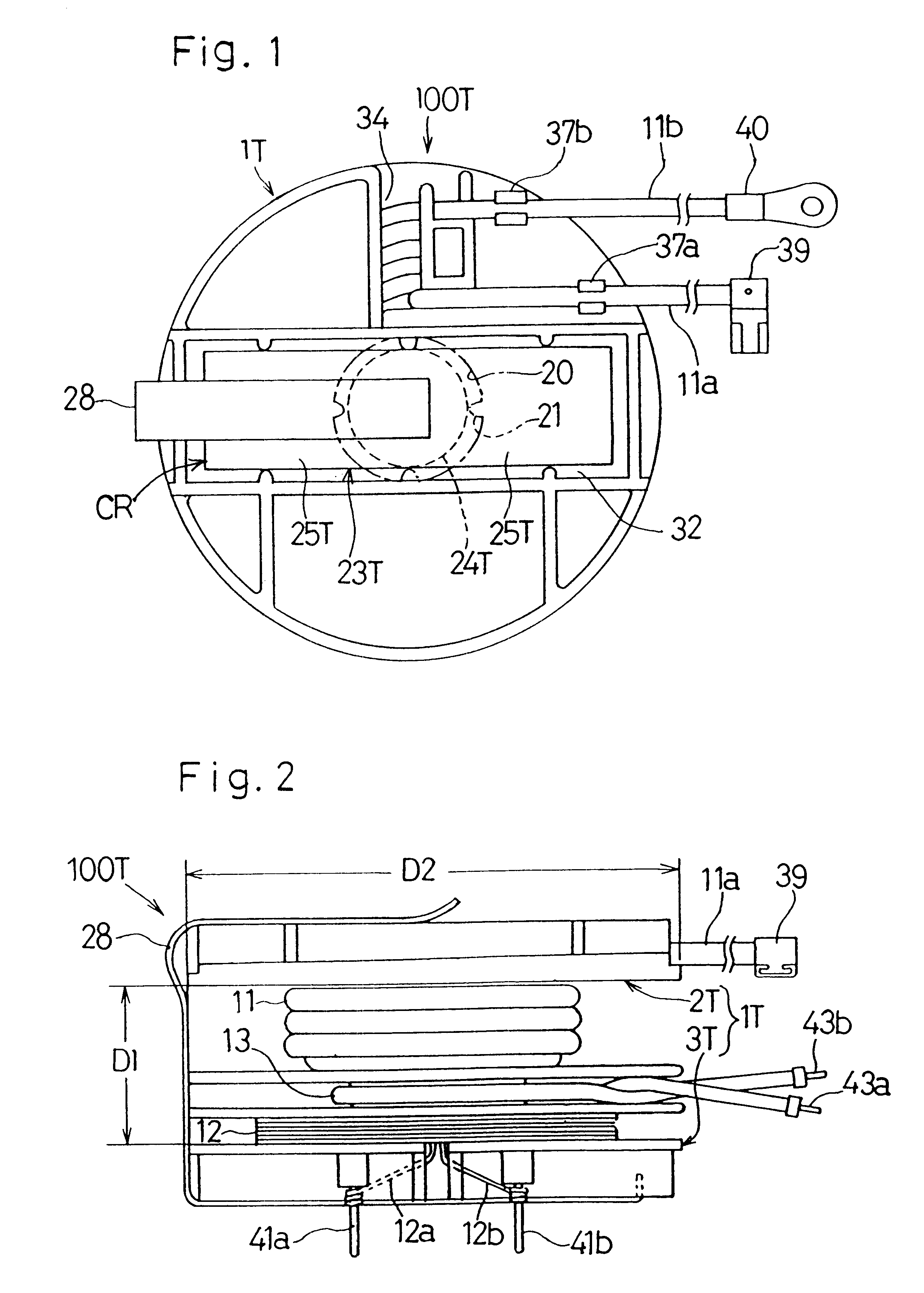
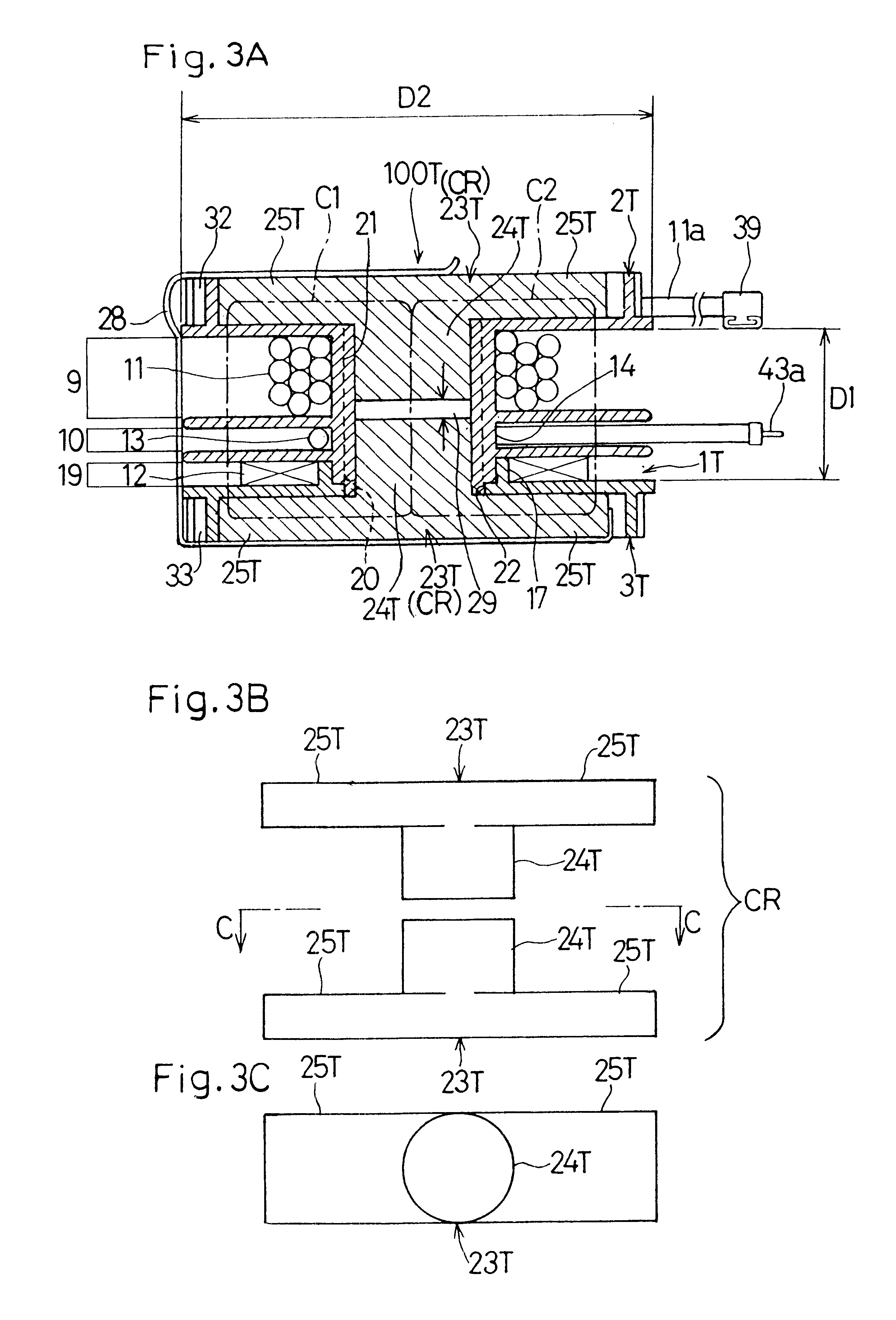
Referring first to FIGS. 1 to 3, there is shown a transformer 100T according to a first embodiment of the present invention. The transformer 100T is a sort of electromagnetic induction devices for driving a magnetron employed in a high frequency heating apparatus generally such as, for example, an electronic oven. The transformer 100T includes a bobbin 1T made of a synthetic resin having an electric insulating property and is, as shown in FIG. 4, made up of axially separated first and second bobbin pieces 2T and 3T. The first bobbin piece 2T includes a hollow cylindrical body 14 having its outer peripheral surface formed integrally with first, second and third annular collars 4, 7 and 8 that lie parallel to each other. This first bobbin piece 2T has a primary winding frame 9 in the form of a primary winding groove bound by a portion of the hollow cylindrical body 14 and the first and second annular collars 4 and 7, and a heater winding frame 10 in the for...

second preferred embodiment

(Second Preferred Embodiment)

The transformer 200L according to a second preferred embodiment of the present invention is shown in FIGS. 6A to 6C. The core assembly CR employed in this transformer 200L is made up of generally L-shaped first and second core pieces 23L and 23L of an identical shape and size. The use of the L-shaped first and second core pieces 23L and 23L necessitates the use of the core chambers 32 and 33 of a shape different from those employed in the previously described embodiment for accommodating the first and second bobbin pieces 2L and 3L forming the bobbin 1L. Other structural features than those mentioned above are substantially similar to those in the transformer 100T according to the previously described embodiment.

As best shown in FIGS. 6B and 6C, each of the L-shaped core pieces 23L and 23L includes a cylindrical core leg 24L and a substantially rectangular core arm 25L having a width equal to or substantially equal to the diameter of the core leg 24L and...

third preferred embodiment

(Third Preferred Embodiment)

The third preferred embodiment of the present invention is shown in FIGS. 7 to 11. As best shown in FIG. 10, the transformer 300T includes the core assembly CR made up of generally T-shaped first and second core pieces 23T and 23T. Referring to FIGS. 7 and 8, the fourth or top annular collar 18 integral with the second bobbin piece 3T positioned above the first bobbin piece 2T is provided at a portion of the outer periphery thereof with a substrate mount 42. This substrate mount 42 is formed integrally with that portion of the outer periphery of the fourth annular collar 18 so as to depend downwardly therefrom and so as to be positioned radially outwardly of the windings 11 to 13. At a location below the fourth annular collar 18, a support projection 8a formed integrally with a portion of an outer peripheral surface of the third annular collar 8 integral with the first bobbin piece 2T is held in contact with an inner side face of the substrate mount 42 th...


PUM

PropertyMeasurementUnit
frequencyaaaaaaaaaa
axial widthaaaaaaaaaa
radial sizeaaaaaaaaaa

Abstract

An electromagnetic induction device having a flat configuration that requires a relatively small space for installation on a circuit substrate includes a flat bobbin (1T) having a length (D1) smaller than a radial size (D2) thereof has primary and secondary windings (11, 12) wound thereon. This bobbin (1T) has coaxially aligned throughholes (20, 22) defined therein into which core legs (24T and 24T) of generally T-shaped first and second core pieces (23T, 23T) are inserted from opposite directions, respectively. Respective core arms (25T, 25T) of the first and second core pieces (23T, 23T) extend parallel to each other.

Description

1. Field of the InventionThe present invention relates to an electromagnetic induction device such as, for example, a transformer utilizing an inverter and, more particularly, to the electromagnetic induction device of a type finding a principal application in, for example, driving a magnetron.2. Description of the Prior ArtFIG. 27 illustrates an inverter-equipped high frequency heating apparatus such as, for example, an electronic oven, of a type disclosed in the Japanese Examined Patent Publication No. 7-40465. This known high frequency heating apparatus includes a rectifying circuit 62 for rectifying and smoothing an electric power from a commercial power source 61, an inverter 63 for converting the rectified and smoothed electric power into a high frequency alternating current of a frequency equal to or higher than 20 kHz, and a transformer 64 including a gapped core and having a primary winding 64p to which the high frequency alternating current is supplied from the inverter 63...

Claims


Application Information

Patent Timeline
Patent Type & Authority Patents(United States)
IPC IPC(8): H01F30/10H01F27/30H01F30/06H05B6/36
CPCH01F27/306H01F30/10H05B6/36
Inventor MIYAZAKI, SINOBUYAMAGATA, FUMIAKISOUMA, HIDEAKIMASUDA, SHINICHITAKASHIGE, YUTAKAKAMBARA, SEIJI
Owner TABUCHI ELECTRIC CO LTD
Why Eureka
Try Eureka