Fluid passage change-over apparatus for medical treatment

a technology of changing equipment and flue gas, which is applied in the direction of engine diaphragms, diaphragm valves, transportation and packaging, etc., can solve the problems of unsatisfactory results, inconvenience, and improper operation of actions, and discourage the application of the conventional system for a new patient. , the effect of requiring extra means

Inactive Publication Date: 2003-07-08
JMS CO LTD
View PDF5 Cites 56 Cited by
  • Summary
  • Abstract
  • Description
  • Claims
  • Application Information

AI Technical Summary

Problems solved by technology

Those actions are troublesome and may be performed improperly.
Also, this will discourage the application of the conventional system for a new, unskilled patient.
However, such an arrangement requires extra means for ensurin

Method used


Image

  • Fluid passage change-over apparatus for medical treatment
  • Fluid passage change-over apparatus for medical treatment
  • Fluid passage change-over apparatus for medical treatment

Examples


Embodiment Construction

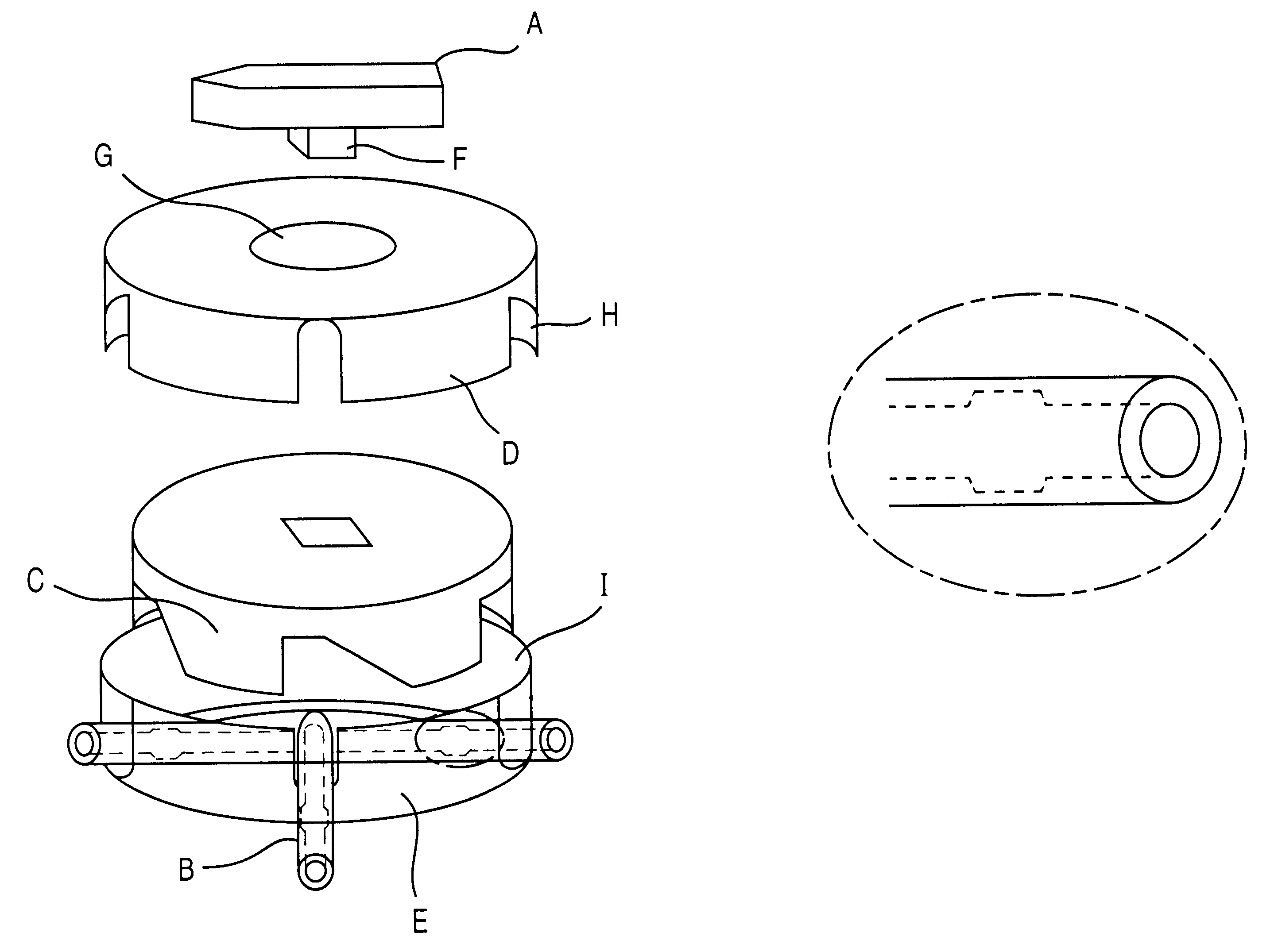
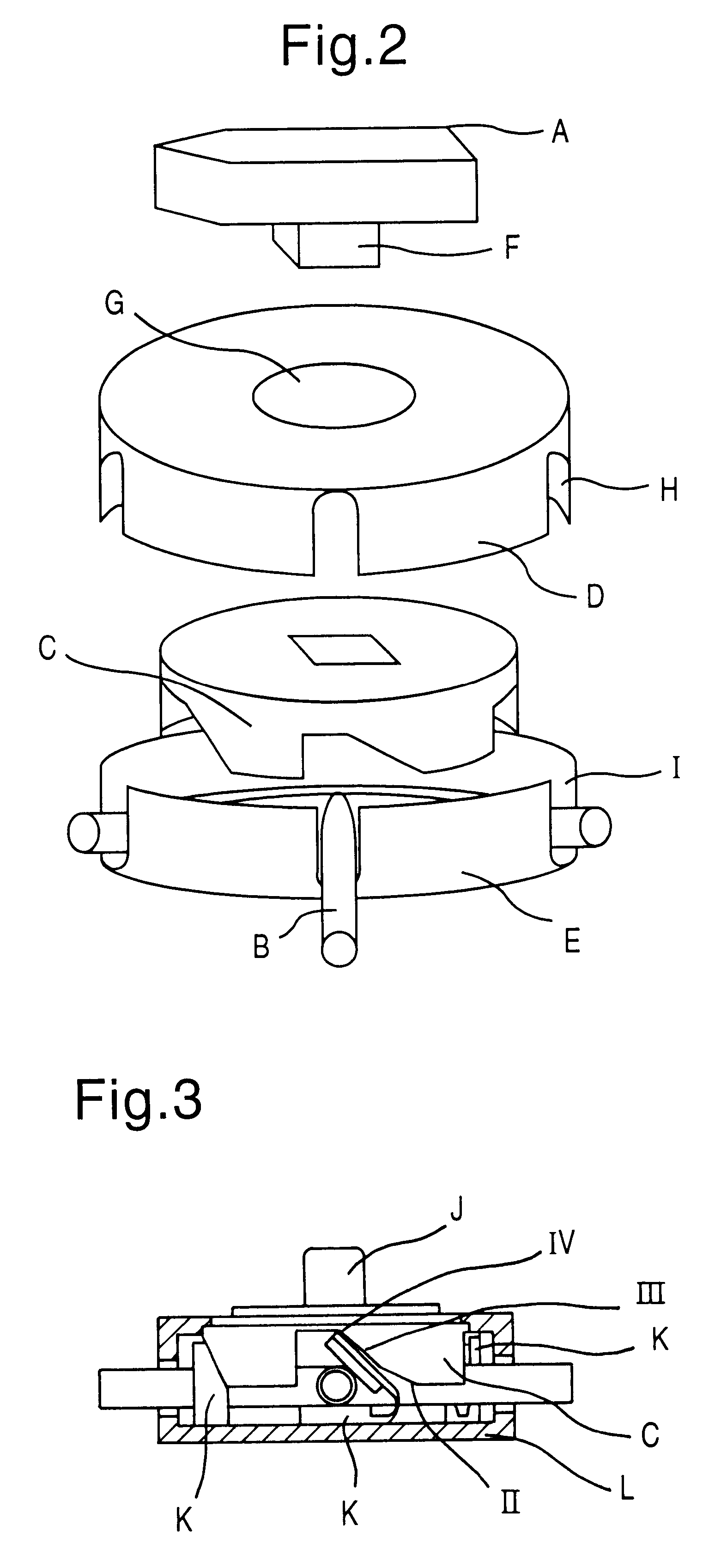
FIG. 2 illustrates a fluid passage switching apparatus comprising a shaft F provided with an operating handle A for pivotably holding a cam C, an upper housing shell D of a cylindrical shape having a through hole G for the shaft F and a tube accepting aperture H provided therein and arranged to fit with a lower housing shell E to form a housing for accommodating the cam, the lower housing shell E of a cylindrical shape having a tube accepting aperture I therein at a location which is opposite to the tube accepting aperture H of the upper housing shell D, and the cam C accommodated in the housing consisting of the upper housing shell D and the lower housing shell E and arranged to be rotated by the movement of the handle A to its selected positions for opening and closing a tube B.

FIG. 3 shows another fluid passage switching apparatus having a cam C and an operating handle J which is formed integral with a shaft joined rotatably to the cam C held to a housing L.

Also, the present inve...


PUM


Abstract

A medical fluid passage switching apparatus comprising: at least, a rotatable shaft F; a cam C which is rotated in relation to the rotating movement of the shaft F to close and open divided tubes for determining a passage of a fluid; and a housing L having tube accepting holes I and so arranged to enable the holding of the cam C, is provided. More particularly, provided are such a medical fluid passage switching apparatus in a continuous ambulatory peritoneal dialysis (CAPD) system and a tube which is decreased in the diameter and/or thinned in the wall at a region where the cam or a combination of the cam and the clamp is engaged for closing and opening.

Description

The first aspect of the invention relates to a medical fluid passage switching apparatus and particularly to a fluid passage switching apparatus mounted to a Y-shaped connecting tube in a continuous ambulatory peritoneal dialysis (CAPD) system, as shown in FIG. 4.The second aspect of the invention relates to components of the medical fluid passage switching apparatus of the first aspect and particularly to a tube employed in the apparatus.The third aspect of the invention relates to a CAPD system employing the medical fluid passage switching apparatus of the first aspect or the medical fluid passage switching apparatus equipped with the tube of the second aspect.PRIOR ART(1) In a conventional back-free, twin-bag system of the CAPD technology, it is necessary to operate three clamps K1, K2, and K3 in a specific order shown in Table 1, wherein said clamp K1 is mounted to a first tube 1 connected at one end to a catheter implanted in the body of a patient, said clamp K2 is mounted to a...

Claims


Application Information

Patent Timeline
IPC IPC(8): A61M1/28A61M39/28A61M39/00A61M39/22
CPCA61M1/28A61M1/288A61M39/223A61M39/285A61M39/286Y10T137/87708
Inventor DOI, HIROYUKISHINMOTO, KAZUHIROFUJII, ZYUNYATANAKA, SEISHIN
Owner JMS CO LTD
Why Eureka
Try Eureka