
Air-fuel ratio controller of internal combustion engines

a technology of air-fuel ratio and controller, which is applied in the direction of electrical control, process and machine control, instruments, etc., can solve the problems of degraded air-fuel ratio control accuracy

Inactive Publication Date: 2003-07-15
DENSO CORP
View PDF8 Cites 20 Cited by
  • Summary
  • Abstract
  • Description
  • Claims
  • Application Information

AI Technical Summary

Problems solved by technology

On this account, it cannot vary the feedback gain continuously in accordance with the operational states of the engine, but has to control the fuel injection at a smaller feedback gain for the sake of control stability, thereby resulting unfavorably in a degraded accuracy of air-fuel ratio control.

Method used


Image

  • Air-fuel ratio controller of internal combustion engines
  • Air-fuel ratio controller of internal combustion engines
  • Air-fuel ratio controller of internal combustion engines

Examples


Embodiment Construction

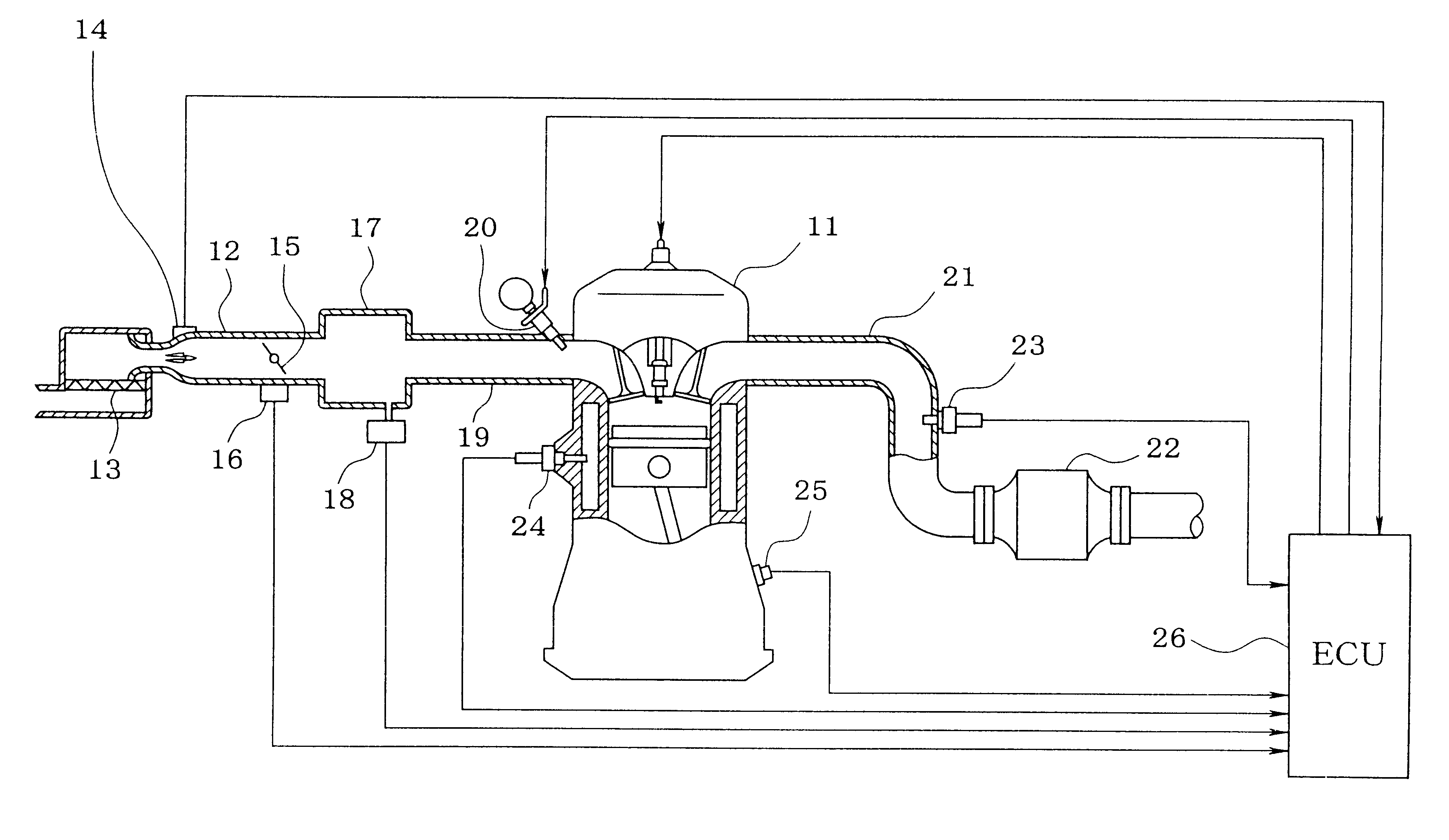
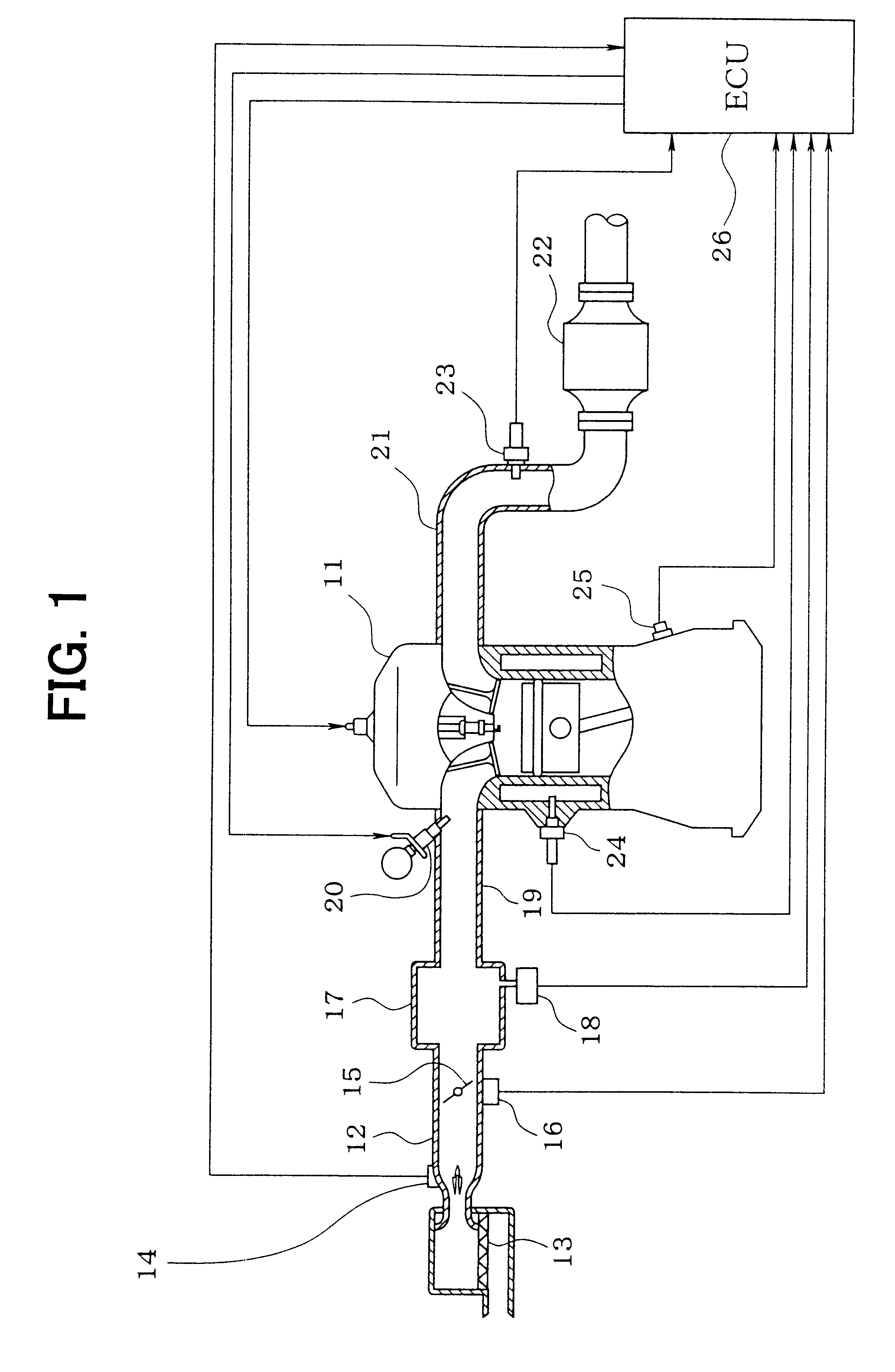
An entire structure of a whole engine control system will be explained with reference to FIG. 1. An internal combustion engine 11 has an air cleaner 13 which is located at the most upstream section of an intake pipe 12, and an air flow meter 14 which is located on the downstream side of the air cleaner 13 for detecting the amount of intake air. Disposed on the downstream side of the air flow meter 14 are a throttle valve 15 and a throttle angle sensor 16 for detecting the throttle angle.

Further, a surge tank 17 is disposed on the downstream side of the throttle valve. The surge tank 17 has the attachment of an intake pipe pressure sensor 18 detecting the air pressure in the intake pipe 12. The surge tank 17 is followed by an intake manifold 19 for introducing air to the cylinders of the engine 11, and on the intake manifold 19 at its positions close to the inlet ports of the cylinders, there are disposed fuel injection valves 20.

The engine 11 also has on an exhaust pipe 21 a catalyt...


PUM


Abstract

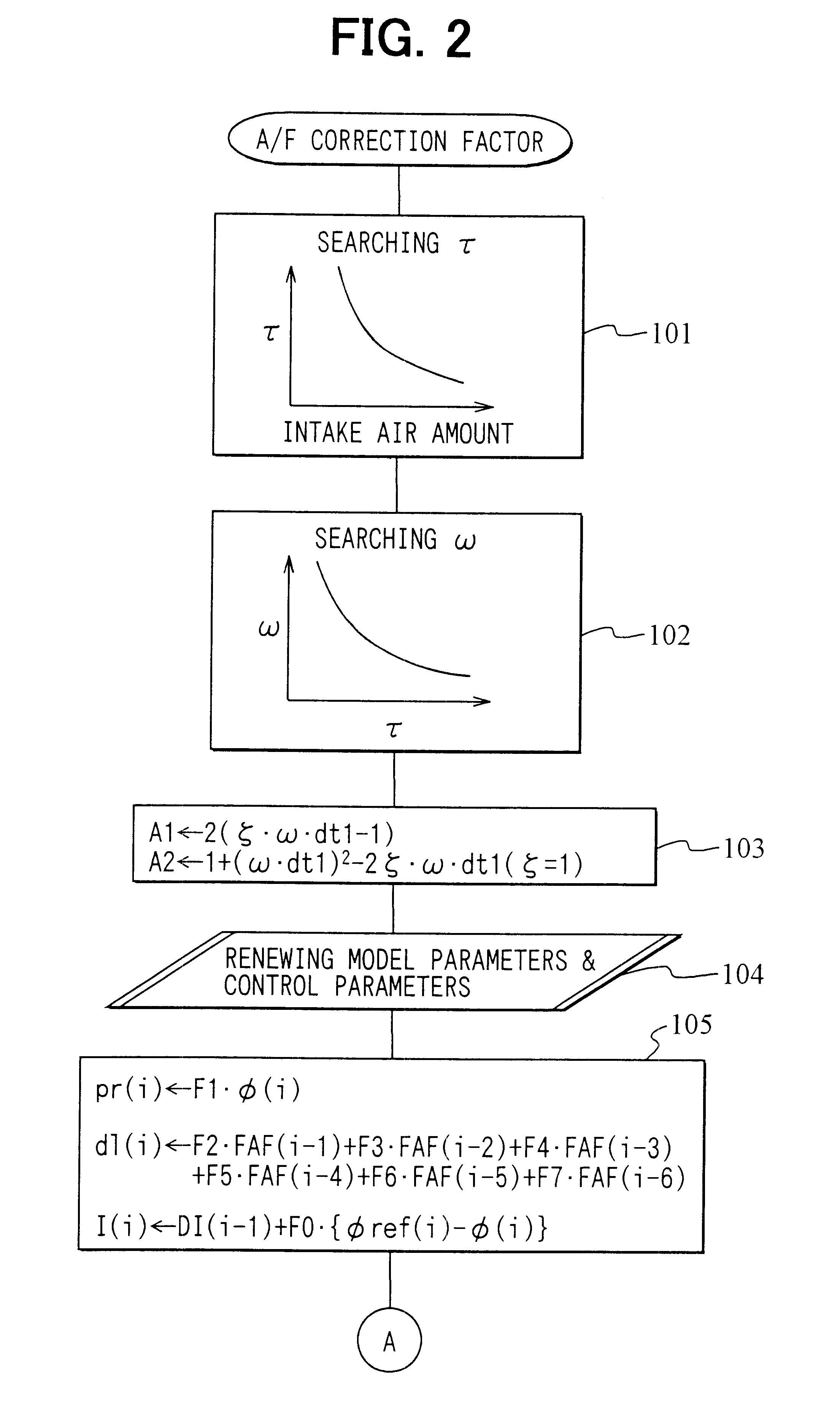
For a control model which simulates a control object ranging from the fuel injection valve up to the air-fuel ratio sensor, coefficients of a characteristic polynomial of the control model are calculated based on the pole arrangement scheme, with roots equal in number to the dead time of the control model being made 0, control parameters are calculated from the coefficients of the characteristic polynomial and from model parameters, and the air-fuel ratio correction factor is calculated from the control parameters. The control model is expressed in terms of a dead time plus first-order lag system, with the total number of roots being set greater by two than the number n of roots which are derived from the time lag, and unknown roots other than those of the dead time are solved based on formulas which are expressed in terms of a second-order lag system.

Description

This application is based on and incorporates herein by reference Japanese Patent Application No. 2000-189734 filed on Jun. 20, 2000.1. Field of the InventionThe present invention relates to an air-fuel ratio controller or an internal combustion engine, which controller controls the amount of fuel injection.2. Description of Related ArtIn recent automobiles, a three-way catalytic converter is located in the exhaust pipe for the cleaning of exhaust gas, and an air-fuel ratio sensor also is located on the upstream side of the catalytic converter to determine the amount of fuel injection based on state feedback for bringing the air-fuel ratio of the exhaust gas close to a purification window (around theoretical ideal air-fuel ratio) in response to output of the air-fuel ratio sensor, so that exhaust gas is cleaned efficiently. The air-fuel ratio control is generally based on a model system of the controlled object ranging from the fuel injection valve down to the air-fuel ratio sensor ...

Claims


Application Information

Patent Timeline
Patent Type & Authority Patents(United States)
IPC IPC(8): F02D41/14G05B17/02G05B17/00G05B23/02
CPCF02D41/1402G05B17/02F02D2041/1415F02D2041/1423F02D2041/1431F02D2041/1433
Inventor DOHTA, HISAYO
Owner DENSO CORP
Learn More