Wavelength selective photocatalytic dielectric elements on polytetrafluoroethylene (PTFE) refractors having indices of refraction greater than 2.0

a technology of photocatalytic dielectric elements and polytetrafluoroethylene, which is applied in the direction of physical/chemical process catalysts, natural mineral layered products, instruments, etc., can solve the problems of loss of physical properties, plastic exposed to ultraviolet light, and a network of fine cracks in plastics exposed to ultraviolet ligh

Inactive Publication Date: 2003-07-29
SIMMON JR FREDERICK LEE
View PDF5 Cites 22 Cited by
  • Summary
  • Abstract
  • Description
  • Claims
  • Application Information

AI Technical Summary

Problems solved by technology

Outdoor lighting fixtures are often exposed to harsh conditions, such as weather, exhaust from vehicles, air pollution from factories, dirt and grime kicked up from the road, etc.
However, if the degradation is too bad, the refractor or lamp cover must be replaced.
Most refractors and lamp covers are made of plastic, but exposure to UV light, such as the UV light present in sunlight, can cause a variety of problems for these plastic covers.
Plastics exposed to UV light develop a network of fine cracks, yellowing, and loss of physical properties.
Though the surface is considered "non-stick" and slippery, static build-up can cause matter to be attracted to the surface and result in some loss in light transmission.
However, the sol-gel process is very limited in that very few substrate materials can be exposed to such high temperatures without deforming, burning, out-gassing or melting.
However, design constraints, such as optically recorded noise patterns, may prevent this construction.
Such diffraction images can make this process unacceptable for roadway lighting fixtures.
Another limitation of the sol-gel method is mechanical abrasive damage to which the film is extremely susceptible.
Still a further problem of the sol-gel method is the tendency of the layers of the film to delaminate both from the substrate and from other adjacent layers therein.
It has been generally accepted that the adhesion between a thin dielectric film and a soft, nonstick material, such as PTFE, would be too weak, and not capable of providing any lasting adhesive bonds.
The arguments would be that any amount of flex in the material causes the thin dielectric film to fracture and delaminate from the PTFE, or that the fracturing would ruin the function of the dielectric element.
In addition, if during its lifetime the dielectric layers become fractured, its function as a photocatalytic dielectric element continues, with some loss regarding transmission of light.
However, the overall performance of the photocatalytic dielectric element exceeds that of organic methods, such as the sol-gel method.

Method used


Image

  • Wavelength selective photocatalytic dielectric elements on polytetrafluoroethylene (PTFE) refractors having indices of refraction greater than 2.0
  • Wavelength selective photocatalytic dielectric elements on polytetrafluoroethylene (PTFE) refractors having indices of refraction greater than 2.0
  • Wavelength selective photocatalytic dielectric elements on polytetrafluoroethylene (PTFE) refractors having indices of refraction greater than 2.0

Examples


Embodiment Construction

The present invention now will be described more fully hereinafter with reference to the accompanying drawings, in which preferred embodiments of the invention are shown. This invention may, however, be embodied in many different forms and should not be construed as limited to the embodiments set forth herein; rather, these embodiments are provided so that this disclosure will be thorough and complete and will fully convey the scope of the invention to those skilled in the art. In addition, the thicknesses of the various layers have been exaggerated in the drawings for the purposes of clarity.

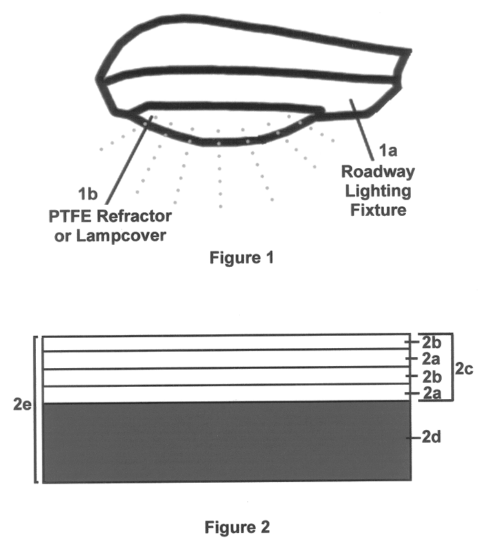
FIG. 1 illustrates a side view of a roadway lighting fixture la having a polytetrafluoroethylene (PTFE) refractor or lamp cover 1b which is coated with the photocatalytic dielectric element according to the present invention. However, the photocatalytic dielectric element can coat a variety of optical substrates other than roadway refractors and lamp covers, such as the windows in a building, a...


PUM

PropertyMeasurementUnit
wavelengthaaaaaaaaaa
temperatureaaaaaaaaaa
angle of incidenceaaaaaaaaaa

Abstract

This invention relates to a photocatalytic dielectric element placed upon polytetrafluoroethylene (PTFE) refractors and lamp covers to provide a self-cleaning surface for use on roadway lighting fixtures. The photocatalytic dielectric element is comprised of a series of hard durable thin dielectric film layers that can be tailored to selectively reflect UV with a plurality of dielectric layers having indices of refraction greater than 2.0. The photocatalytic dielectric element is otherwise transmissive to light at all other wavelengths. In addition, the photocatalytic dielectric element can concentrate photons generating from the light fixture, or from direct sunlight within a narrow range of wavelengths on the outer surface of the polytetrafluoroethylene refractor or lamp cover. In turn this promotes photocatalytic reactions that decompose bacteria and other organic contaminates that contact the polytetrafluoroethylene refractor or lamp cover where the photocatalytic dielectric element is placed upon, thus, making the light fixture self cleaning. The photocatalytic dielectric element can be placed on what is termed as, "difficult to adhere to substrate materials", such as the polytetrafluoroethylene, while maintaining good adhesion without delamination, in addition to most any other substrate material. The photocatalytic dielectric element preferably has been deposited on the surface of the polytetrafluoroethylene refractor by dual alternating low-pressure environment deposition techniques.

Description

BACKGROUND OF INVENTIONThe present invention relates generally to self-cleaning coatings and, more particularly, to the adhesion of photocatalytic dielectric elements placed upon polytetrafluoroethylene (PTFE). The invention reflects UV light while concurrently inducing photocatalytic reactions of anatase TiO.sub.2 on the surface of an optical substrate (PTFE), and is used for producing self-cleaning refractors and lamp covers on roadway lighting fixtures.Outdoor lighting fixtures are often exposed to harsh conditions, such as weather, exhaust from vehicles, air pollution from factories, dirt and grime kicked up from the road, etc. All these factors and more contribute to reduce light output from roadway lighting fixtures. Therefore, the refractors or lamp covers on the fixtures require continuous cleaning. However, if the degradation is too bad, the refractor or lamp cover must be replaced. Most refractors and lamp covers are made of plastic, but exposure to UV light, such as the U...

Claims


Application Information

Patent Timeline
Patent Type & Authority Patents(United States)
IPC IPC(8): B08B17/00B08B17/06B08B7/00G02B27/00B01J35/00
CPCB08B7/0035B08B17/06G02B27/0006B01J35/004Y10T428/24967Y10T428/24942Y10T428/2495G02B1/18Y10T428/3154Y10T428/31544
Inventor SIMMON, JR., FREDERICK LEE
Owner SIMMON JR FREDERICK LEE
Why Eureka
Try Eureka